Previous: Section 29 |
| |
|
3/18/08: Sidetracked: CNC Router
Before I even started this plane I knew I wanted to try to make a fiberglass instrument panel. I started contemplating how I was going to do this and have it look at least a little bit professional. My first thought was to use clay. I made an ugly prototype with some clay I bought at the hobby store. The results were okay, but I knew that it wouldn't be good enough for making a fiberglass mold.
What I really wanted to do was to design the panel in 3D on the computer. The challenge is to then render that 3D into the real world. So I started searching for ways to mill a 3D shape into wood or foam. I found some commercial products, but they all started at around $10,000 and went up from there.
Since I am building my own airplane why not build my own CNC router as well? I did some lengthy searching and finally settled on a design that would allow me to cut the complete instrument panel at once without the need to reposition the stock. The design came from David Solsylva, who sells a set of plans from his website at http://www.solsylva.com. |
| |
|
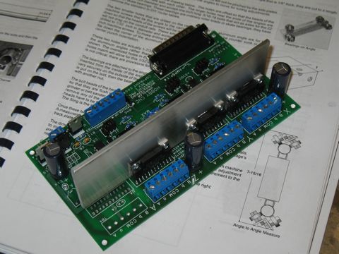
I placed an order for the plans for the router table and then went searching for a solution for interfacing the router to the computer. There are several options here, but one in particular was a kit, which I decided would be preferable since I apparently can't do anything the easy way!
The driver board and the stepper motors came from http://www.hobbycnc.com. I went with the 3-axis board with 305in/oz stepper motors.
Assembly and testing of the board was straightforward. It worked the first time I applied power. |
 |
| |
|
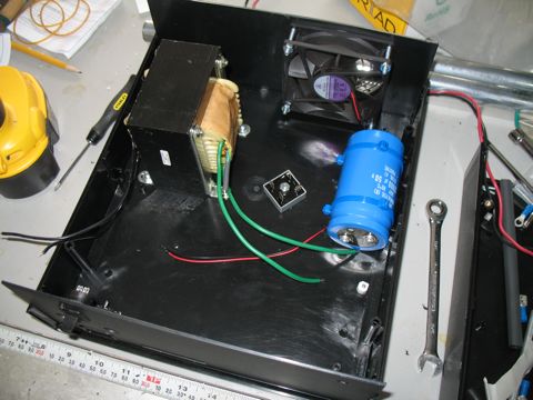
The driver board needs a pretty substantial power supply to be able to drive three 3 amp stepper motors at 24 volts. I built the power supply according to the directions supplied with the HobbyCNC board. The power supply design is straightforward, but the parts are bigger than I am used to.
Dealing with AC is always a bit freaky for me, but it all turned out fine. |
 |
| |
|
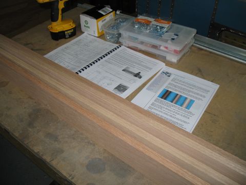
A trip to Lowes and Home Depot produced just about all of the raw materials I needed. The Solsylva plans have a fairly complete list of materials, which I followed with a few exceptions.
One change I made was to switch the leadscrews from standard hardware store threaded rod to ACME precision leadscrews. I purchased these from McMaster/Carr. I went with the 3/8-10 2-start variety. These cost a bit more, but should give me a good speed boost.
I bought the leadnuts from http://www.dumpstercnc.com. |
 |
| |
|
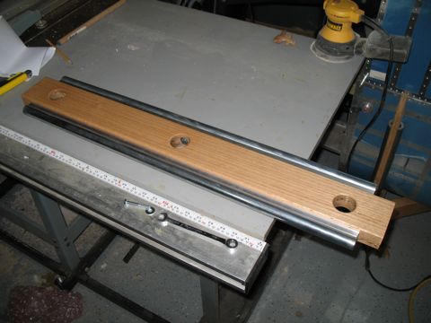
The plans call for standard construction lumber to be used for the assembly. I went with oak. I glued up 3/4" pieces to create the 1 1/2" stock needed for the gantry and the frame. This should make for a much more stable assembly.
The rails are made from EMT (conduit). |
 |
| |
|
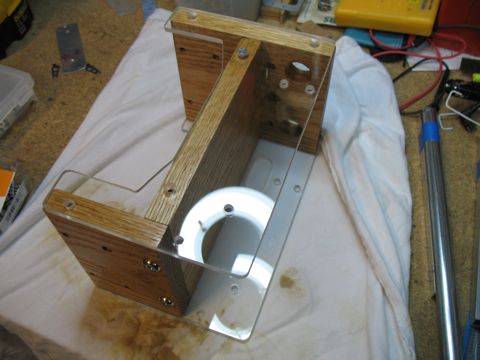
The router rides on a carriage that slides back and forth on the gantry. I made the sides of the carriage out of Plexiglass. |
 |
| |
|
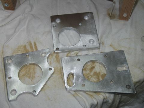
These are the motor mounts. I made these from 1/4" thick aluminum.
|
 |
| |
|
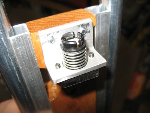
The leadnuts take a little extra thought because the plans call for something different. I ended up using aluminum angle for most of the leadscrew brackets. Here is the one attached to the z-axis.
|
 |
| |
|
Smooth travel is obtained by using rollerblade bearings. I bought these from http://www.vxb.com/.
The standard ones are for 1/4" hardware. I also bought a dozen or so bearings with a 3/8" ID to work with the ACME leadscrews. |
 |
| |
|
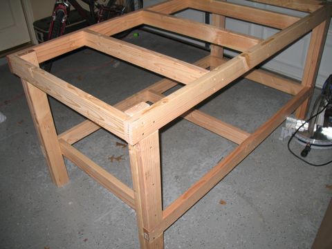
This thing is going to be pretty large if it's going to be able to cut a 44" wide instrument panel. That's another modification I made to the plans. The overall size for the Solsylva router is 25"x37". I am extending mine to 25"x48".
So I decided I will need a workbench for this dude to sit on. I made this from standard 2x4s and MDF for the top. |
 |
| |
|
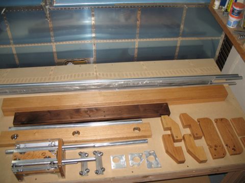
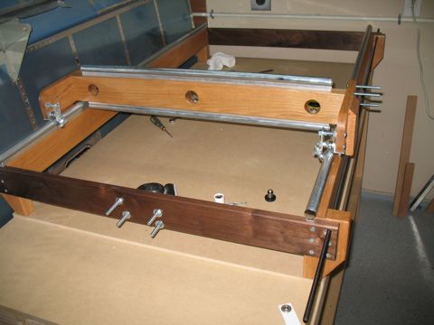
Now that I have all the parts fabricated, and a workbench to build it on, it's time to assemble the beast. I have sealed all of the wood with spray urethane.
|
 |
| |
|
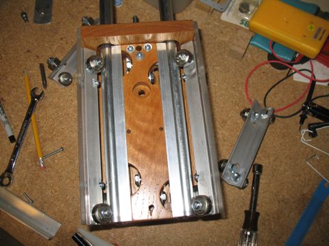
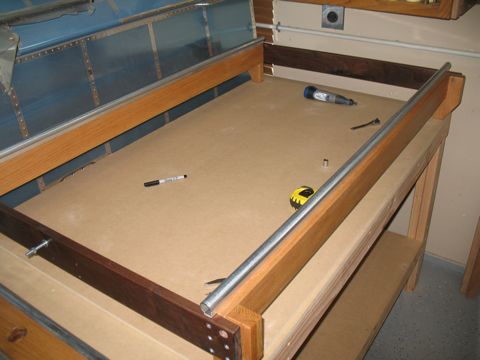
The x-axis rails are complete.
|
 |
| |
|
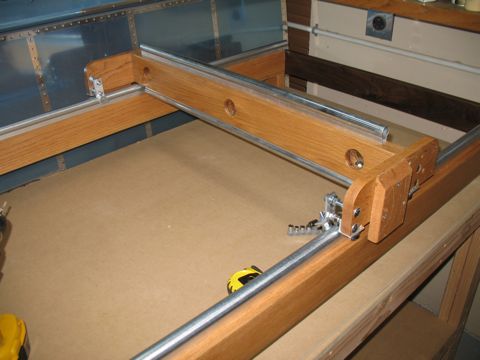
This is the gantry. This design is somewhat unique becuase it rides above the table, leaving the sides open for long or unusual shaped stock. The table can also be raised to accommodate particularly thick 3D work.
|
 |
| |
|
There are two x-axis leadscrews: one on each side. This keeps the gantry from getting out of alignment.
|
 |
| |
|
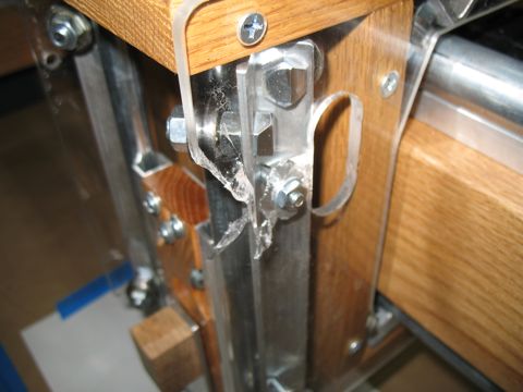
Soon after tightening the tensioning nuts on the z-carriage, I noticed that the plexiglass had cracked on one side. It doesn't really affect the operation too much, but I will need to repalce it. I hope to be able to cut a new piece using the router.
|
 |
| |
|
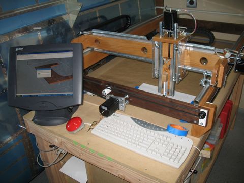
The computer is an old Pentium PC. I think it's 1.8ghz single core processor with 256mb of RAM. So, it's not that great by today's standards, but it does the job.
I bought a touchscreen monitor off eBay to act as the control panel for the router. This is good because it's difficult to find a place for a mouse that isn't covered in dust. Besides, touchscreens are cool.
I'm going to need to figure out something for the keyboard. |
 |
| |
|
The software that runs the router is Mach3.
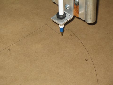
One of my first tests was using a pen to trace the DXF of the standard instrument panel. I then placed the actual part from Vans onto the tracing, and it matched perfectly. So I think this has a chance of actually working!
|
 |
| |
|
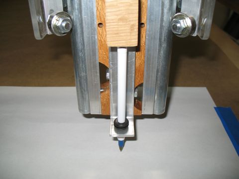
Here's my pen attachment. It has a spring in the block at the top.
|
 |
| |
|
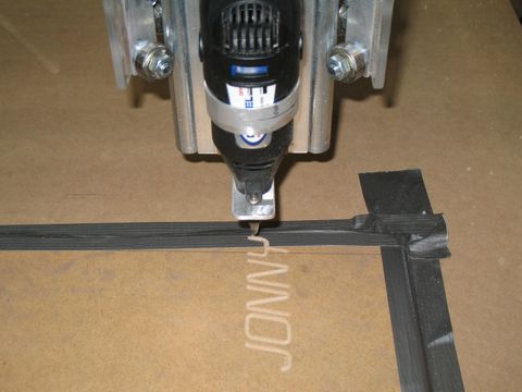
Next I attached a Dremel tool. I used a similar strategy as with the ink pen. I bent a piece of aluminum to hold the tip of the router. Dremel tools all have a 3/4" threaded collet at the tip so they can be attached to various add-on products. So I made my adapter with a 3/4" diameter hole and I captured the aluminum with the collet.
I used this setup to write the names of anyone who would come out to the garage and watch. It is actually sort of fun to watch this contraption write your name. |
 |
| |
|
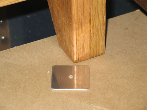
I noticed that the router wasn't exactly true to the table top, so I made some shims out of different thicknesses of aluminum to raise the legs the correct amount.
|
 |
| |
|
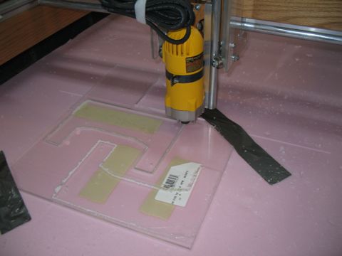
Time to move up to the production router. I bought a Dewalt trim router and installed it on the carriage.
Here is the first "real" part I made on the router. It's a replacement side panel for the one that cracked. I sat down with the dimensions for the part and drew it in Sketchup Pro. I exported it as a DXF and then used Sheetcam to generate the G-code. Finally I loaded the G-code into Mach3. I used a straight bit in the router and made three passes to cut the 1/4" plexiglass. I found that this seems to work best. Move the router at a fast rate, but only remove a small amount of material with each pass.
I still have a lot of learning to do, but I think this thing will work out great for my purposes. |
 |