Previous: Section 42 |
| |
|
5/19-6/4/09 - Instrument Panel
I have gone around in circles trying to come up with a really cool looking composite instrument panel for the RV-10. I have designed several and cut two of them with my CNC machine, only to toss them out because of one reason or another. The biggest problem is that it is way more difficult than I expected to get a nice finish. So I was almost resigned to just use the stock metal panel when I came across a posting on VAF about a carbon fiber instrument panel that was almost exactly the same as what I was trying to produce. After drooling over the images and kicking myself for wasting so much time trying to make my own, I finally decided to find the source for this panel. |
 |
| |
|
It turns out that a fellow RV-10 builder named Geoff Combs produced these. He is selling them through SteinAir. So I quickly made a call to my buddy Stein and in no time I had my very own copy of this wonderful panel.
If you want more information, check it out at Stein's website.
This panel is designed so that it can be set in place without making any changes to the plane. It is the same shape as the panel it replaces; however, it is a little bit taller. Permanent installation requires a bit more work, and I will try to describe my experiences as I replaced the stock panel with this one. |
 |
| |
|
There are a few options you can choose with this panel. For example, I believe you can ask Stein to give you a version of this panel that works with a throttle quadrant. Also, you can choose whether or not to install the center console. Since I am using the standard vernier-style throttle controls and I want to use a center console, I just ordered the standard setup.
|
 |
| |
|
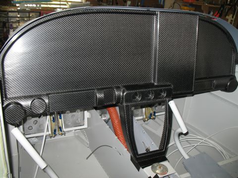
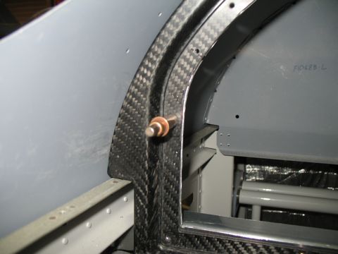
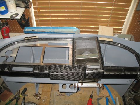
An important feature of this panel to me is the large space on the left side of the panel. This allows me to install both EFIS screens to the left of the radio stack. Also, the radio stack is angled towards the pilot. I have this setup in my other plane and I really think it is the way to go.
Finally, I am very impressed with the quality of this product. The panel is made from carbon fiber, so it is strong and lightweight. It's also very cool looking. |
 |
| |
|
6/6 - 7/4/09 - Panel Installation - 10 hrs
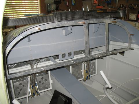
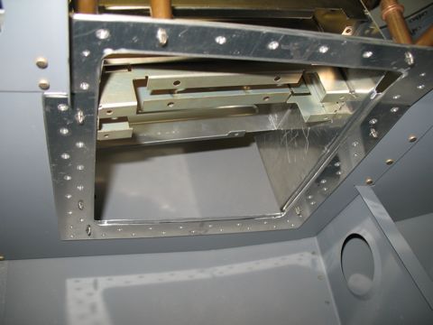
The first thing to realize is that the carbon fiber panel must be secured to the existing structure. So I started by cutting a new instrument panel from a solid sheet of aluminum. This new panel is taller than the stock panel. I also modified the F1003B lower flange to simplify the installation.
This panel can now be thought of as the skeleton of the new panel. |
 |
| |
|
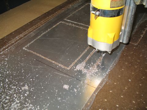
I cut a set of panel inserts on my CNC router out of plexiglass. I used these as templates so I could visualize the screw locations that need to be drilled into the substructure.
|
 |
| |
|
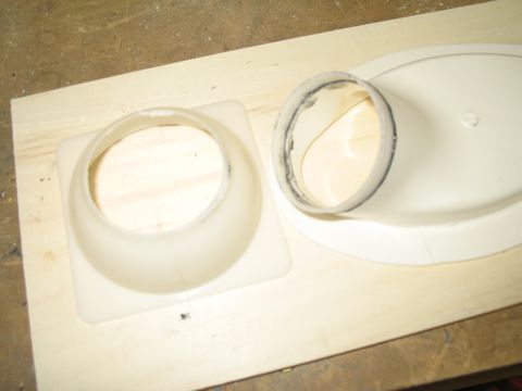
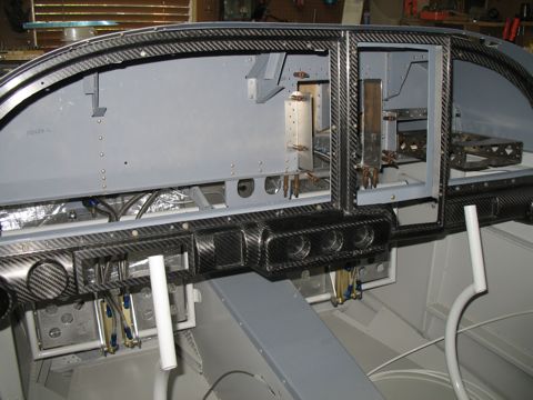
I modified the NACA ducts since I no longer need the large flange for the vents. |
 |
| |
|
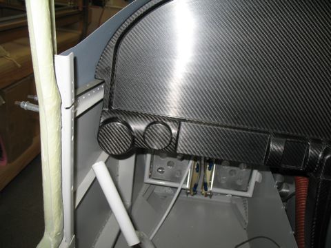
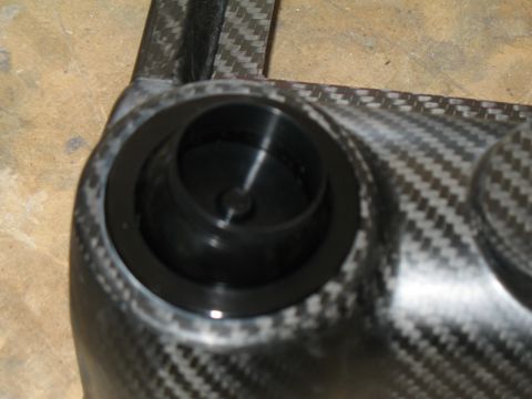
Instead, here are the new anodized eyeball vents that fit nicely into the new panel.
|
 |
| |
|
| |
 |
| |
|
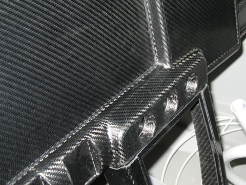
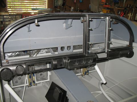
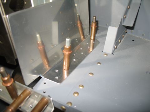
After drilling a few holes it is possible to start to see the idea...
|
 |
| |
|
Then I cut panel blanks out of aluminum...
|
 |
| |
|
7/23/09 - Panel Work - 8 hours
|
 |
| |
|
| |
 |
| |
|
| |
 |
| |
|
| |
 |
| |
|
8/6/09 - Panel Work - 4 hours
Time for a test fit. Here are the steps involved in installing the panel. Each item is layered on top of the previous one.
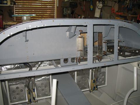
So we start with the lower flange. I flipped my flange over and installed nutplates. |
 |
| |
|
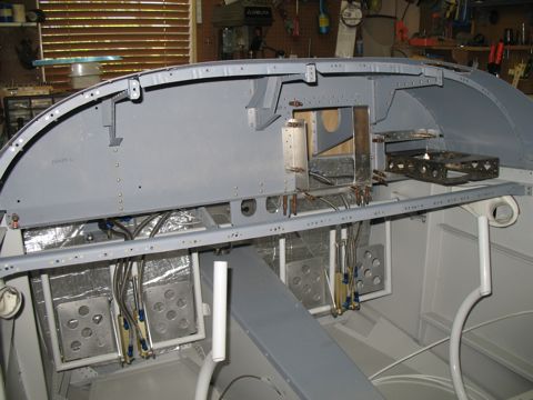
Next, the forward fuselage top is installed...
|
 |
| |
|
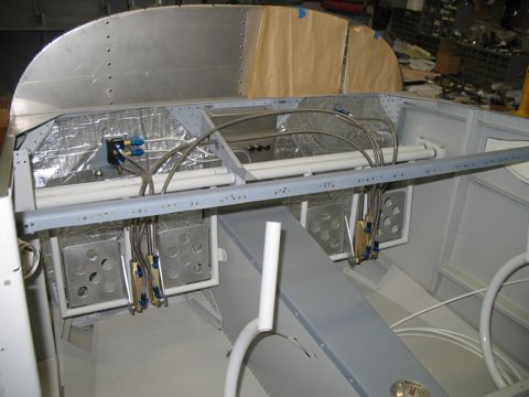
Next, the subpanel is installed and screwed to the ribs and to the flange around the fuselage top and the lower flange.
|
 |
| |
|
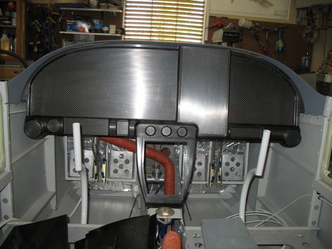
The composite panel goes on next. It is secured using some countersunk screws around the perimeter of the panel insert flanges.
You might notice in this picture that I have added some supports to the subpanel to support the avionics stack.
I'll get back to this stuff soon. |
 |
| |
|
Next: Section 43
|
 |