Previous: Doors, etc. |
| |
|
5/28-5/29/10 - Door Latch - 10 hrs
Recently Van's has issued a mandatory service bulletin concerning the door latch. They also sent out a repair kit and some instructions on how to add a secondary latch mechanism to the center of the door. I didn't like the looks of that solution very much but I didn't have any better ideas. That all changed when I saw a post from Sean Strasburg with a link to a video showing his solution to the problem. Apparently enough other people liked it too because he started selling kits for his solution.
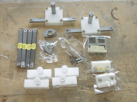
So I bought Sean's kit. If you are interested go to www.PlaneAround.com. Here's what it looks like. |
 |
| |
|
The kit is a modification to the standard Van's kit. So the first thing I had to do is to cut the long pushrod. This makes a secondary pushrod that goes between the new latch and the door handle. |
 |
| |
|
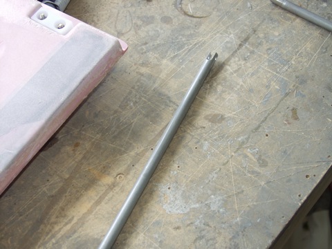
The cut is made. |
 |
| |
|
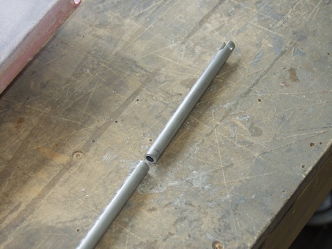
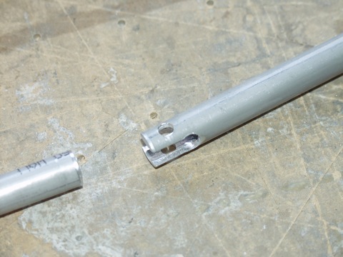
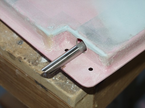
Then I had to add a slot that matches the one from the factory. I did this by drilling a 1/4" hole through the middle of the tube and then cutting the notch from the end of the tube to the edge of the hole.
|
 |
| |
|
The new clevis pin hole is larger than the 1/8" hole on the factory end.
|
 |
| |
|
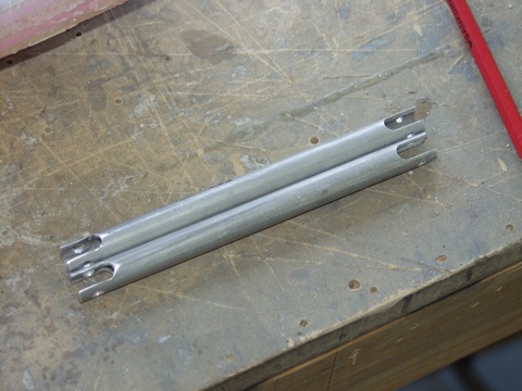
After some work I had two small pushrods.
|
 |
| |
|
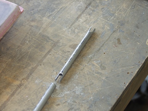
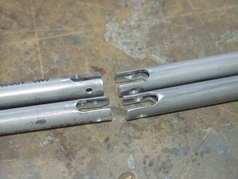
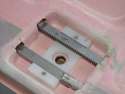
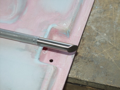
Next I had to notch the remaining long pushrod in the same manner. Here are the resulting notches that I made. |
 |
| |
|
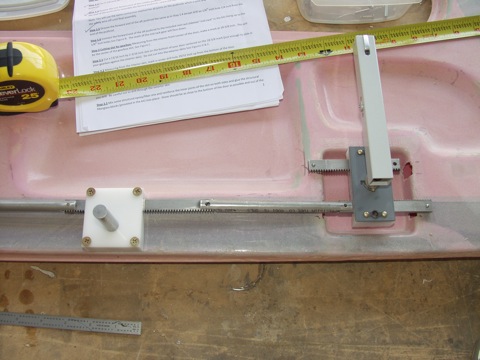
Since I was curious about how everything was supposed to fit together, I laid all the parts out on top of the door.
|
 |
| |
|
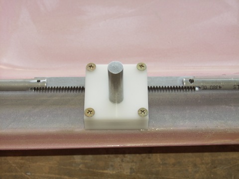
As you can see, the aft pushrod is where all the excitement happens. The fore-aft motion is translated into rotational motion by the new gearbox.
|
 |
| |
|
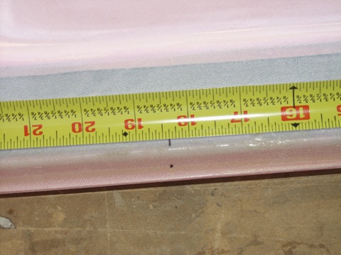
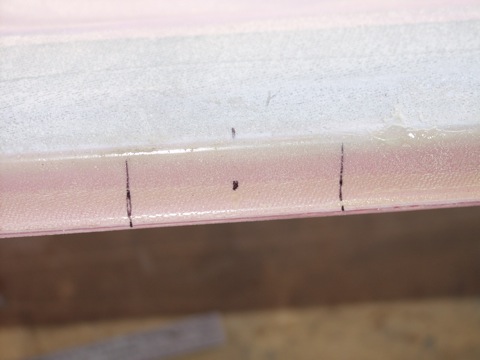
Next, I marked the location at the bottom of the door where the gearbox will be installed.
|
 |
| |
|
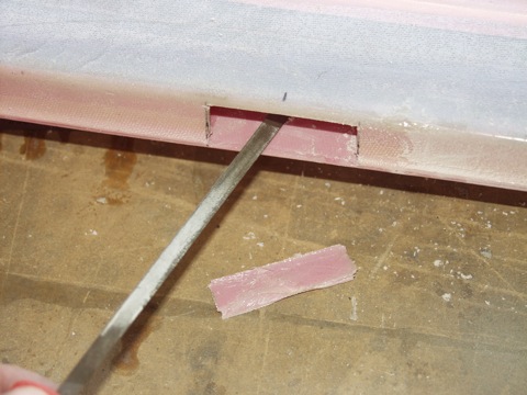
This slot needs to be just big enough for the gearbox to fit. I figured out that the height dimension is pretty irrelevant because you basically have to remove all the material between the inside and outside door skins in order for the gearbox to fit.
|
 |
| |
|
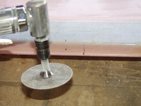
I started by drilling holes in the four corners. I then used a die grinder and a Dremel tool to make the cut.
|
 |
| |
|
This was the first try. I cut the slot according to the dimensions in the instructions, but it wouldn't fit.
|
 |
| |
|
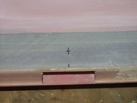
Here is the slot after a bit of clean up with a file.
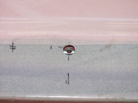
Next, I marked the location to drill a 1/2" hole for the shaft.
|
 |
| |
|
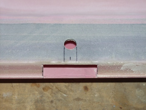
I drilled the hole and then marked where I needed to make the final cuts.
|
 |
| |
|
As you can see, I nearly went through the outer skin with my unibit.
|
 |
| |
|
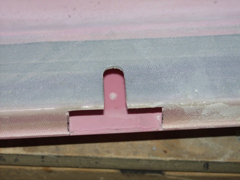
Here is a trial fit. The slot is a bit tight, but it fits.
|
 |
| |
|
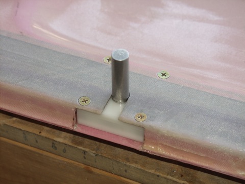
Next, I used the top cover of the gearbox, along with the shaft, to match-drill the holes for the mounting screws.
|
 |
| |
|
This is sort of hard to show in a photo, but the next step was to epoxy in the reinforcement blocks.
|
 |
| |
|
After the epoxy cured, I countersunk the screw holes. This actually works better with the gearbox in place as it provides a pilot hole for the countersink bit.
|
 |
| |
|
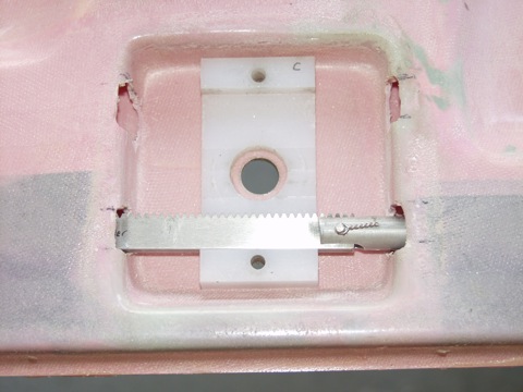
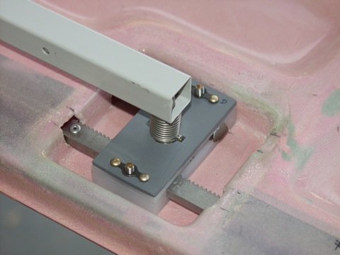
| Here's the gearbox mounted in place. |
 |
| |
|
Sean sends a new set of guide blocks for each door. These have an extension that I guess allows the pins to be retracted further into the door.
I had already installed the factory blocks so I removed those. Then I had to enlarge the exit hole quite a bit. |
 |
| |
|
The aft block was pretty easy to install. Not too much shaping was required to get a good fit.
|
 |
| |
|
The forward guide block was a bit more of a challenge because of the unusual shape of the opening in the door.
|
 |
| |
|
5/30/2010 - Door Latch - 3 hours
The pushrods are temporarily attached to the racks so you can determine the motion and the extents of the travel. |
 |
| |
|
I abandoned the factory racks and installed the new ones attached to the pushrods.
|
 |
| |
|
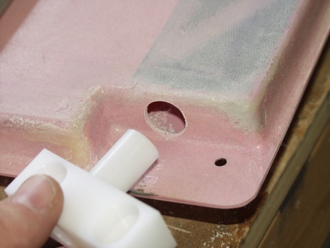
This is the access hole that I had to drill in the door to provide access to the connection between the middle pushrod and the gearbox rack.
|
 |
| |
|
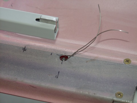
Sean provides a pin with a spring loaded ball bearing on one side. This allows it to be installed "blind" through the access hole.
|
 |
| |
|
| |
 |
| |
|
| |
 |
| |
|
The pushrods are a little long now. I'm going to need to trim them quite a bit.
|
 |
| |
|
The forward pushrod doesn't extend quite as far as the aft one, but it too will need to be trimmed and re-tapped.
|
 |
| |
|
6/3-6/11/2010 - Door Stuff - 10 hours
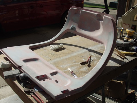
I decided to go ahead and order the latch pins and Delrin guide blocks from Sean because the ones I had ordered previously were going to require some machining to get them to fit. So while I waited for the order to be delivered, I worked on filling the pits and valleys in the left dor. I used Super-Fil, which is pretty easy to work with. |
 |
| |
|
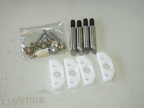
Here's what I got from Sean (www.planearound.com). The guides are made of delrin and the pins are stainless steel.
|
 |
| |
|
I cut the pushrods to length and tapped them for the threads on the pins.
|
 |
| |
|
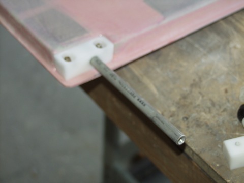
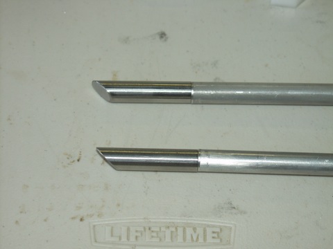
The pins have a bevel machined on one end. To get these to face forward, I had to make adjustments to the actual length of the pushrod using a file.
|
 |
| |
|
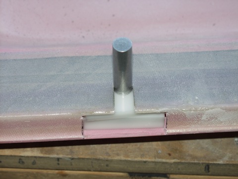
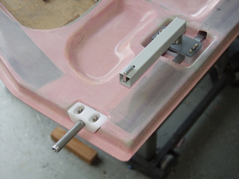
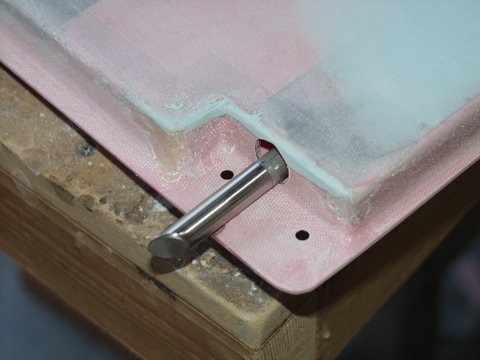
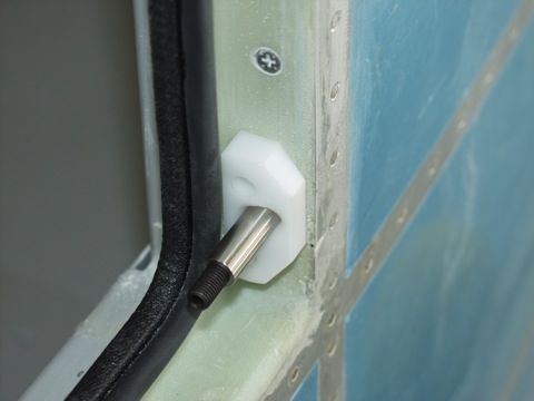
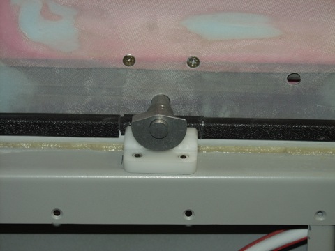
Here it is in the correct position. I will eventually put threadlocker on the threads but for now they are just hand tightened.
|
 |
| |
|
| |
 |
| |
|
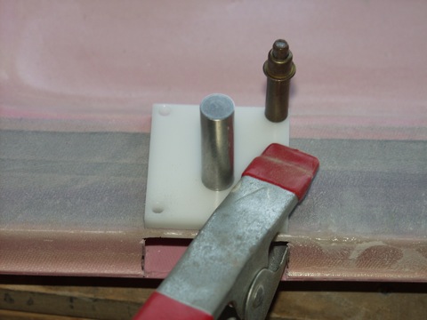
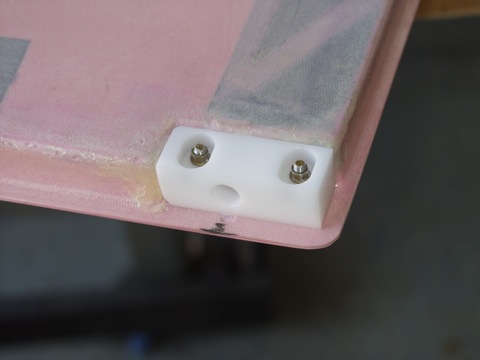
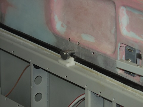
I used a pin to set the location of the delrin guide blocks. I then clamped the block in position to drill one hole. With the first hole drilled I installed the hardware and then drilled the second hole.
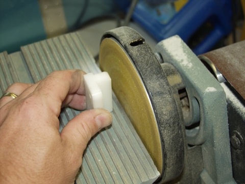
On the first attempt, the door would not close. I quickly figured out that the new guide blocks were too tall. The blocks had to be adjusted for a perfect fit. I did this using my belt sander. |
 |
| |
|
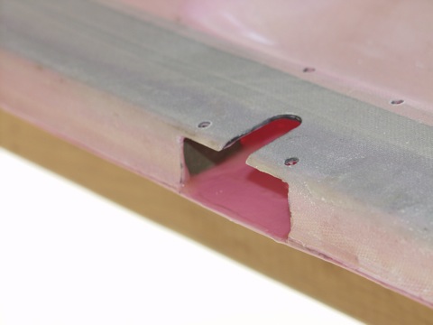
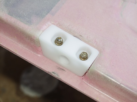
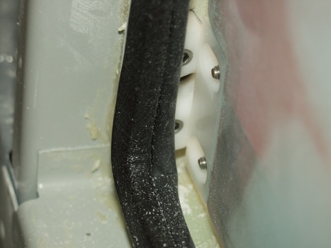
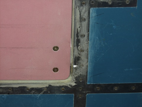
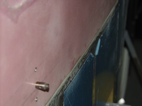
Here is a picture of the interference I am referring to.
|
 |
| |
|
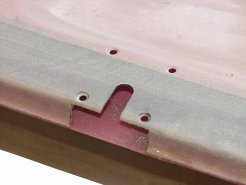
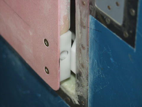
I had to reduce the thickness of the aft guide block until the door would close.
|
 |
| |
|
| |
 |
| |
|
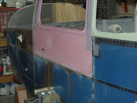
Here's something I'm going to need to work on. The door gap is inconsistent around the edges of the door.
|
 |
| |
|
| |
 |
| |
|
The final step is to install the Delrin block where the new latch grabs and pulls. The first test fit showed that they needed to be a little bit shorter. So I made the adjustment with the belt sander.
|
 |
| |
|
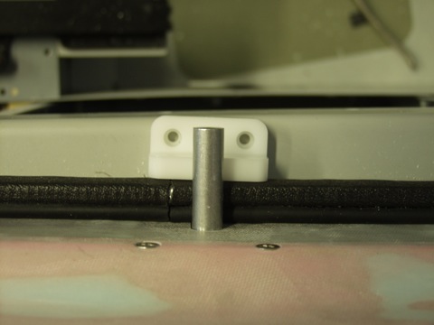
Here is the door in the closed and latched position. The new center latch mechanism is in the center of the door and it really does a good job of helping the door line up properly.
|
 |
| |
|
| |
 |
| |
|
Next: More Door Work
|
 |
| |
|