Previous: Section 28 |
| |
|
Section 29
When building one of these planes there are a few particularly unpleasant but unavoidable tasks. First was the riveting the trailing edges of the empennage. Then there were the fuel tanks. Now we come to the section that includes the bending of the longerons. Eventually I'll be dealing with the cabin top and the doors. For me it's best just to get it over with. |
| |
|
1/29/08 - Bending Longerons - 2 hrs
The longerons are the long pieces of aluminum angle that stretch from the firewall all the way back to the tailcone. In the RV-10 there are two longerons per side because of the door openings.
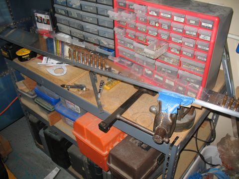
Van's was nice enough to include a template made of aluminum. This template is used to establish the shape of the bend that I need to try to accomplish. The process is to put the angle in the vise and then whack it with a big mallet. Then move it an inch and whack it again. While doing this the angle has a mind of it's own and wants to also bend in the vertical dimension. So then I have to put it in the vise and apply force to "unbend" the vertical. It can be frustrating. |
 |
| |
|
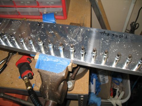
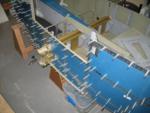
These are the upper longerons. They start behind the door frame and end at the tailcone. The template includes holes to drill that will eventually match up with the longerons already mounted in the tailcone.
Notice in this picture that some holes are not drilled on this side. That's because the baggage door is only on the left side of the plane. Gotta watch out for those tricky comments in the instructions. |
 |
| |
|
1/30/08 - Longerons - 2 hrs
I found it helpful to mark the template on both sides to indicate which part I was bending, just to avoid the confusion.
This is a serious workout. With the angle in the vise, apply force in the direction of the bend and strike the angle with a mallet. I really need an extra set of hands for this.
At this point I realized that at some point I inadvertently used the 9' piece of angle that is intended for the longeron. Fortunately Todd lives only a few miles away, so I borrowed his and ordered a replacement. Thanks Todd! |
 |
| |
|
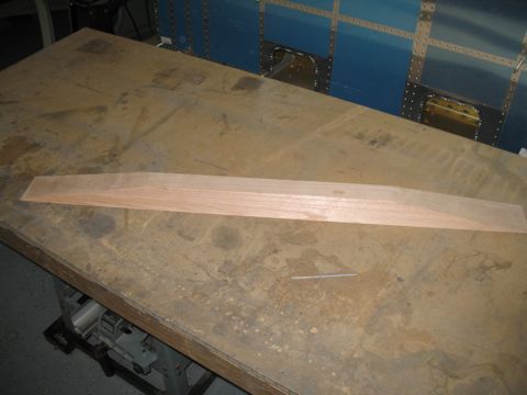
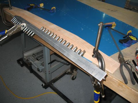
1/31/08 - Clamping Block - 2 hrs
At this point the instructions call for a special clamping block to be manufactured by the builder. The instructions call for a 1 1/2" x 3 1/2" x 46" long piece of hardwood. That's a nice dimension as it corresponds to a typical construction 2x4, but then it says it needs to be hardwood. The last time I checked they don't make 2x4s out of hardwood. So, I laminated two pieces of 3/4" oak to arrive at the required size. Then I cut the angles into the block using my tablesaw and the bandsaw.
It really is a work of art. Too bad it doesn't go on the plane. It's just a tool used for the bending process. |
 |
| |
|
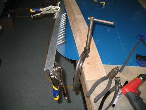
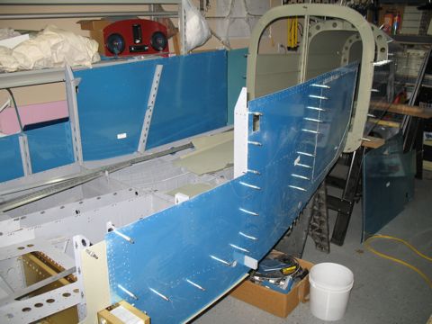
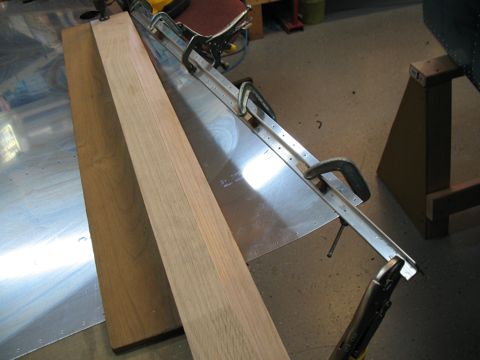
2/1/08 - Bending the Skins - 4 hrs
These bends are supposed to match the radius of the tailcone on the back end of the fuselage. So the clamping block is clamped down to the table and the builder is left with the unnerving task of attempting to bend aluminum in 3D.
|
 |
| |
|
| |
 |
| |
|
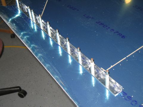
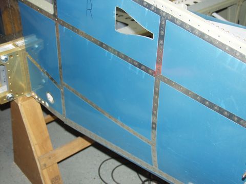
Several test-fits and adjustments later, the aft skins are adequately bent.
|
 |
| |
|
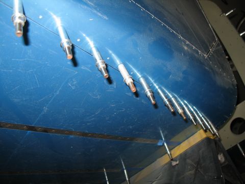
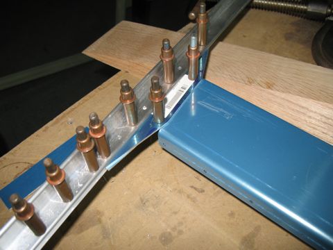
This is where the accuracy of the bend is put to the test. The row of rivets must match up to the rivet holes on the underside of the fuselage.
|
 |
| |
|
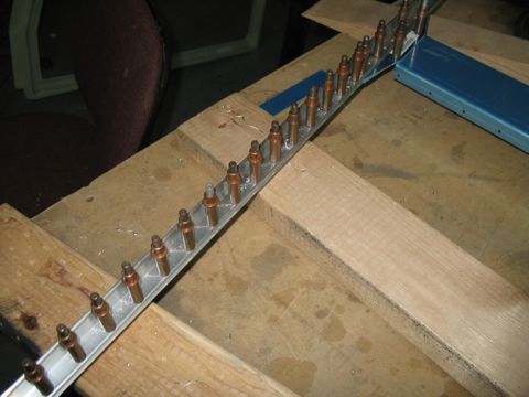
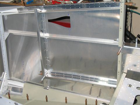
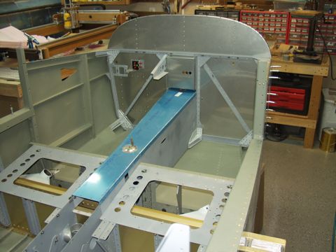
This is the left upper longeron. There are two pieces that are riveted to the longeron to span the opening of the baggage door.
|
 |
| |
|
| |
 |
| |
|
There are also a couple of baggage floor angles that are drilled to the side skins at this point.
|
 |
| |
|
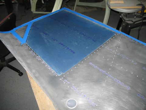
2/2/08 - Match-drilling the sides - 1 hr
Notice that I used blue masking tape to mask off the holes that I'm not supposed to drill at this time. I did this because I'm getting forgetful. |
 |
| |
|
2/5/08 - Forward Skins - 2 hrs
The instructions tell me to modify the clamping block at this point, but since I plan to pass it along to another builder I didn't want to mess it up, so instead I used it in conjunction with a piece of 1/4" hardwood and it worked fine.
These are the forward side skins. The bend must match the radius of the firewall. |
 |
| |
|
It's important to pay particular attention to the aft corners. They can't be creased, but they need to be bent all the way around almost to 90°.
You may notice the radius that has been sanded onto the clamping block. This is hopefully enough to keep the skin from making a crease. |
 |
| |
|
2/8/08 - More Bending, etc. - 7 hrs
I continued with the bending of the forward skins, with a few test fits to make sure I was getting it right. Next came the bulkheads and channels.
The channels are bent according to the instructions using the vise and a big wrench. Who knows if I got mine exactly right, but they appear to look similar to the plans, so we'll live with them for now. |
 |
| |
|
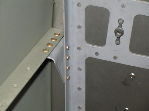
The 1040 and 1041 side channels are the aluminum pieces that attach to the steel brackets on the firewall.
|
 |
| |
|
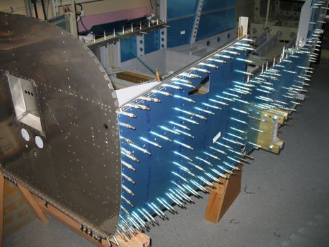
2/9/08 - Match drilling, etc. - 8 hrs
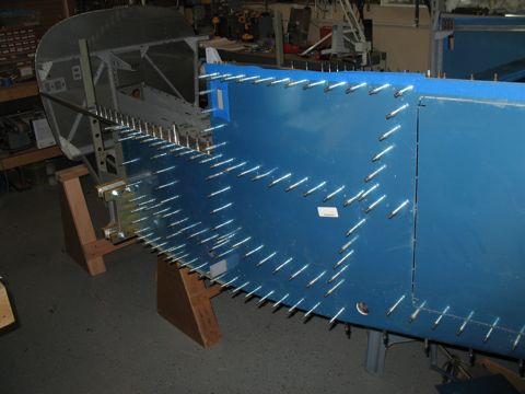
It's great when I get to spend an entire day working on the project. Today I started by match-drilling all of the skins to the structure.
At one point I had every single #40 cleco I own in use on the plane. That's around 800 clecoes, I think. |
 |
| |
|
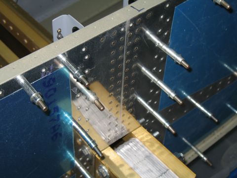
The hardest part is match-drilling the longerons. I switched to a new drill bit when I started the day, but it was definitely dull by the end.
|
 |
| |
|
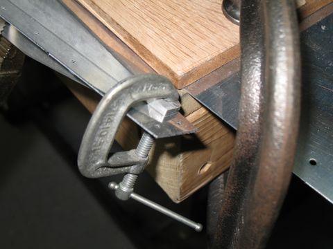
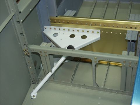
2/10/08 - Drilling & Stuff - 4 hrs
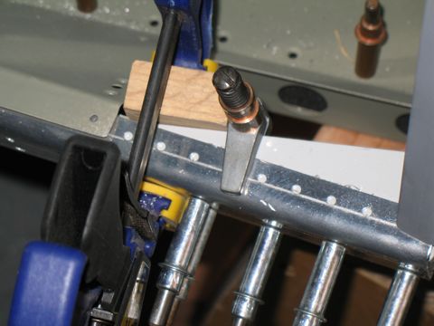
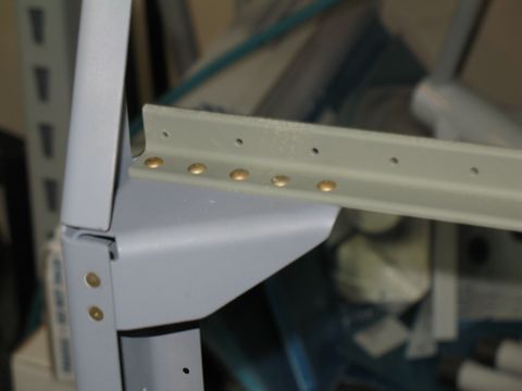
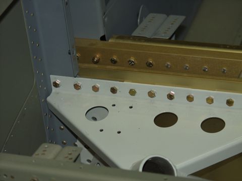
Here's something I want to spend some time discussing, because it would be easy to mess this up. The firewall brackets are made of steel, and don't necessarily parallel the sides of the fuselage. So it would be very easy to accidentally drill the holes too close to the edge of the bracket, which would not be a good thing. So, to make sure I had adequate edge distance for the holes, I clamped the firewall brackets both horizontally and vertically, and checked the distance visually before drilling the holes. |
 |
| |
|
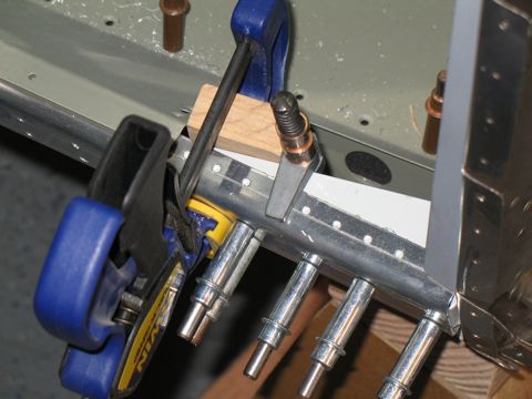
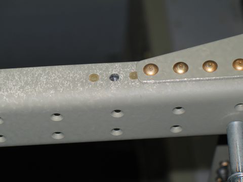
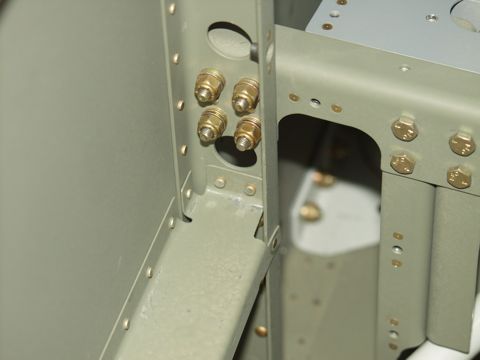
The same thing is true for the lower firewall brackets. Pay attention to these or you'll be replacing the brackets for sure. |
 |
| |
|
2/15 - 2/16/08 - Dimpling, etc. - 12 hrs
I didn't take the time to document every step in this process, but basically I machine countersunk the longerons, dimpled the structure and the skins, and prepped the parts for priming. |
 |
| |
|
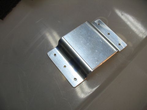
2/17/08 - Parking Brake/Fuel - 6 hrs
Just as I was getting ready for primer, the weather turned nasty and I had to wait. So, time to get sidetracked on another part of the project.
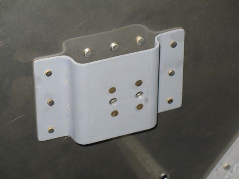
This is what I did to install the Matco parking brake valve. I started with the bracket that is used for a carbureted plane that I'm not going to use. I cut it down to size, removing about 3/4" of material from each end. |
 |
| |
|
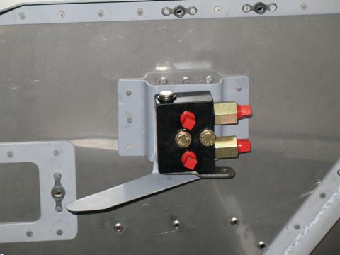
The brake hose attachment was removed from the firewall and I riveted the new bracket in it's place.
|
 |
| |
|
I am still working on the bracket for attaching the actuator cable, but basically it will be sandwiched under the valve and will be bent to provide a mounting place for the cable. Stay tuned for a better version.
|
 |
| |
|
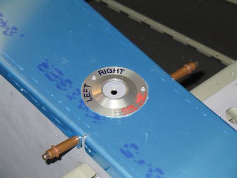
I can't believe I didn't take pictures of this, but I will try to go back and document it later. I relocated the fuel selector bracket so that I could use the Andair fuel valve. It fits just above where the Van's valve would have been. |
 |
| |
|
2/18/08 - Assembly - 6 hrs
I finally got a good weather day, so I primed all of the parts from this section. I also ran out of 2-part primer, so I guess I need to make another trip to the paint supply place.
Now it's time for final assembly. |
 |
| |
|
| |
 |
| |
|
| |
 |
| |
|
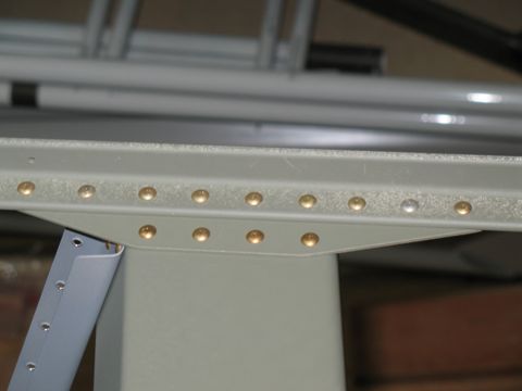
Although not mentioned in the instructions, there are a few platenuts on the upper channels that will definitely be easier to install now. So, I went ahead and riveted these prior to attaching the channels to the structure.
|
 |
| |
|
| |
 |
| |
|
2/19/08 - Riveting the Skins - 1 hr
All the work I've been doing over the past few days has aggravated my back, so I tried to take it easy today. I did start to rivet the skins, but I didn't get very far. |
 |
| |
|
2/20/08 - More Riveting - 2 hrs
I made some more slow progress on riveting the skins. I think I'm going to need to get one of my kids to help me rivet some of this. |
 |
| |
|
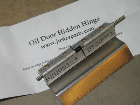
Oh, I bought this cool hinge for my oil door. It should be a perfect compliment to the Hartwell flush latches I bought at Oshkosh.
|
 |
| |
|
| |
 |
| |
|
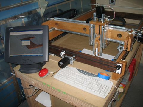
2/21 - 3/15/08 - Sidetracked
I took what turned out to be almost a month so I could build a CNC router. Hopefully it will come in handy.
|
 |
| |
|
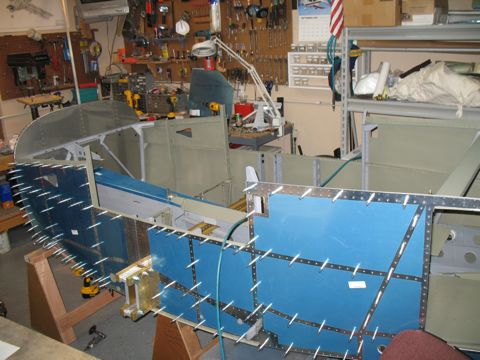
3/16 - 3/30/08 - Riveting - 5 hours
Time to get back to the plane. Over several short sessions I finally completed riveting the side skins. |
| |
|
4/6/08 - Vents, Mounts, Floors - 8 hours
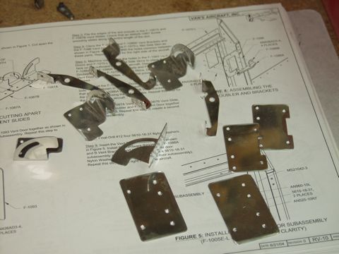
Let me just state right now that I don't like these vents. I think they are cheesy and I can't imagine that they will be acceptable when I'm finished, but oh well.
Here are all the parts, all deburred. Time to get busy assembling them. |
 |
| |
|
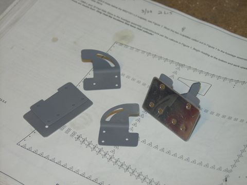
After some primer and a few rivets this is what they look like. Okay, this is one of them done with the other one in pieces still, but you get the idea.
|
 |
| |
|
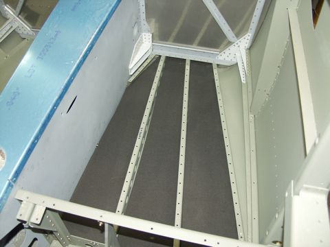
Here is a look at the foam insulation I put in the floor area. It's the stuff that Spruce sells with the sticky back.
|
 |
| |
|
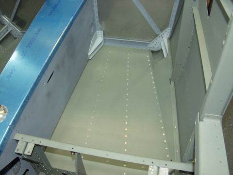
And here is the floor installed with pop rivets. I have one of those pneumatic pop riveters from Harbor Freight and occasionally it shoots a cloud of oil out of the exhaust port. That's what you see on the tunnel on the left side. Yuck.
|
 |
| |
|
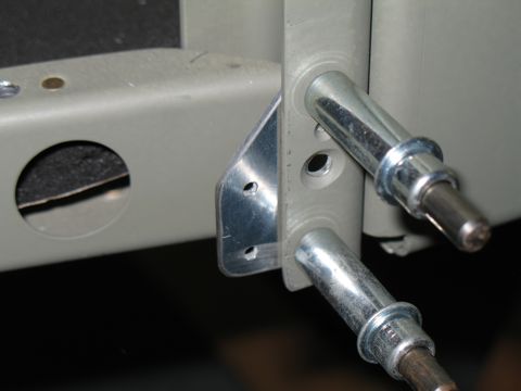
With the floors installed I can finally install the main gear mounts.
|
 |
| |
|
| |
 |
| |
|
| |
 |
| |
|
4/7/08 - Fwd Fuse Ribs - 1 hour
With the gear mounts in place I could finally install the ribs that were left out during the initial riveting of the side skins. Here I have riveted the left one into place. |
 |
| |
|
| |
 |
| |
|
| |
 |
| |
|
4/8/08 - Random Rivets - 2 hours
I got Tim to help me with a few more difficult to reach rivets and I am finally drawing section 29 to a close. This was a lot of work and I had a bit of a self-imposed delay added to the time because of the work I did on the CNC thing, but now I am happy once again to be making progress. |
 |
| |
|
Next up: Section 30: Steps
|
 |