Previous: Overhead Console |
| |
|
2/1 - 25/2010 - Wiring - 20 hrs
This month I've been primarily working on wiring the panel.
The process started with a paper design. During the past few months I have carefully documented the connections on each device. There are a lot of connections to make and I am somewhat concerned that I will omit wires that later I'll wish I had included. So I decided to approach it from the standpoint of devices and their connectors. For example, I have an SL-30 page that shows the two connectors. I went through the installation instructions for the SL-30 and made a diagram of each connector, pin by pin. I then listed each of the wires leading in and out to other devices. My other devices have similar pages. So when wiring, all I have to do is look at each page for the two devices. |
| |
|
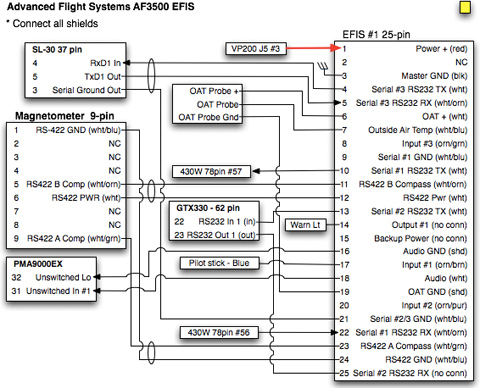
Here is an example of the page for the EFIS. As you can see, I have the 25 pin connector represented on the right side. I illustrate the connections to the other devices by showing an abbreviated pin list for that device. So, in this example I show the connections to the SL-30, but only the three pins that are important on this page. I have another page showing the SL-30 listing all pins in the 37 pin as well as all pins on the 15 pin connector.
Eventually I will probably list the wire color for each connection on each of these pages. The wiring diagrams were done on the computer so they constitute a "living" document that I will continue to update as I do the actual wiring. |
 |
| |
|
It is interesting to me to read the installation documentation for each device. By looking at the pinouts I have found features that would have otherwise gone unused. For example, the audio panel can drive a cabin speaker, so I've decided to install one in the overhead console. This should come in handy when trying to listen to the ATIS or whatever.
Tools
The next thing in the process was to collect the necessary wiring tools that I will need. I have all the tools that I bought when I built the -9a, so I really didn't need to buy many tools. Here is a short list of the tools necessary: a good pair of wire cutters, a wire stripper, various crimpers for molex, fast-on, d-sub, ring terminal, and coax connectors. Also necessary is a soldering iron and a heat gun for the shrink tubing. It is also important to have a good multimeter for checking voltages as well as continuity. |
| |
|
Some of my tools came from local electronics stores, but most of them came from Steinair.
I did buy a couple of things that I thought would make things go more smoothly. I bought a coax stripper to make it easier when installing the BNC connectors on the RG-400 coax. I also got a cool label maker that prints on the side of shrink tubing. This is what I will use for labeling the wires. It is really fun to use too. The only real downside is the cost of the printable shrink-tubing. I got mine from Amazon.com.
|
|
| |
|
Supplies
A few years ago while working on my RV-9A, I bought a "kit" from Steinair because I needed basically everything so I figured it would be good to just get the majority of it all in one package. The kit from Stein included a basic set of tools, a collection of connectors and ring terminals, fuse blocks and fuses, switches, and tefzel wire. This turned out to be an economical and convenient way to get most of what I needed for that plane.
For this plane I wanted to have colored wires, so I called Stein and asked for 20 feet each of 20 different colors of tefzel wire. (http://www.steinair.com)
I also order supplies from B&C (http://www.bandcspecialty.com). They carry a lot of items that are difficult to find anywhere else. I ordered a bunch of RG-400 coax, two and three conductor shielded wire, connectors, switches, ring terminals, etc. |
| |
|
Wiring Harness
Although I am wiring things myself, I did receive a bit of a head start when I ordered my EFIS from Advanced Flight Systems. It came with a wiring harness for the primary display. It still has to be wired to my other devices. The harness was built by Steinair and all the wires were well labeled. I'm glad to have this part done because it gives me a chance to see how the pros do things. |
| |
|
2/13-2/27/10 - Wiring - 20 hours
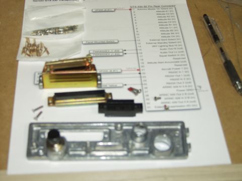
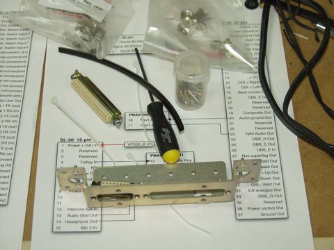
So with no other excuses remaining, it's finally time to do some wiring. For each device I printed out it's diagram and then found its connector kit. |
 |
| |
|
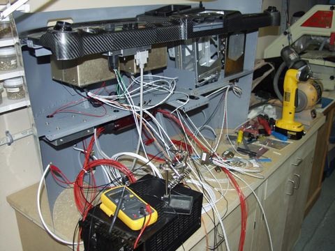
The upper forward fuse is still off the plane, making it much more convenient to run the wires.
I started with the VP200 system. I placed my bench power supply on the bench (heh!) and connected the VP200 to the supply. The VP200 is where all my power is routed, so the process begins by running a red power wire from one of the VP200 connectors to the appropriate power pin on whatever device I am interested in powering. |
 |
| |
|
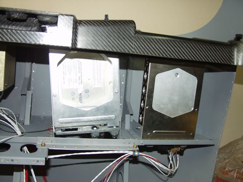
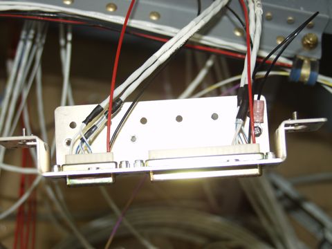
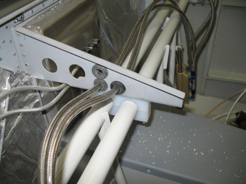
I got this panel from Geoff Combs and it has an angled section for the avionics stack. This is great but it means some interesting work on the subpanel to provide adequate support for the trays. So here is a picture of the angled trays. I have installed some angled pieces to the subpanel.
On the right of the picture is my transponder. It is connected to the EFIS and to the Garmin GPS to display traffic. It gets the encoded altitude from the EFIS. It also has audio out for alerts or something, so I ran a shielded wire to the audio panel. Finally, it supports a remote IDENT button. |
 |
| |
|
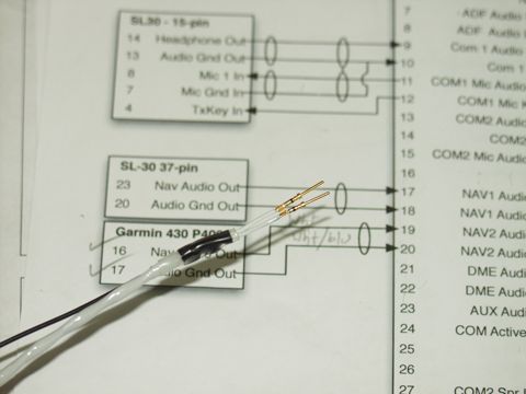
This one is for the SL30. It connects to the EFIS via an RS232 serial connection.
|
 |
| |
|
This fancy tool is used to crimp the pins for the D-Sub connectors.
|
 |
| |
|
| In many cases the shields of all the shielded wires need to be connected together. This can be messy, so I am using a scheme that I stole from Matt Burch. He uses solder sleeve, which I don't have. So instead I just solder the pigtail and then use shrink tubing to terminate the shield. Matt has a nice website and he's a good guy too. I've met him a few times at OSH, and I'm sure his RV-7 will be awesome. |
 |
| |
|
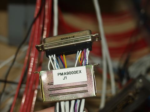
So before long I start to have a fairly good number of wires coming into the audio panel, and the ground wire pigtails seem to multiply.
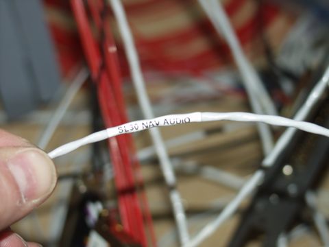
Here is one example of how I am using my label maker. |
 |
| |
|
...and here's the shrink tubing that I printed on the labelmaker.
|
 |
| |
|
| |
 |
| |
|
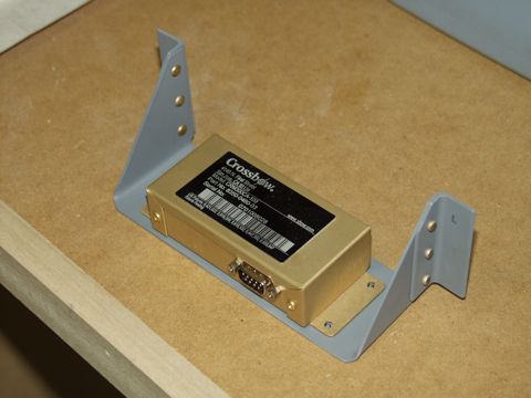
Here's the bracket I built for my magnetic compass...
|
 |
| |
|
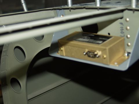
...and I mounted it to a bulkhead in the tailcone.
|
 |
| |
|
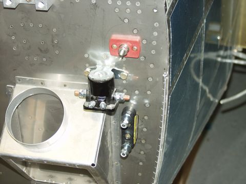
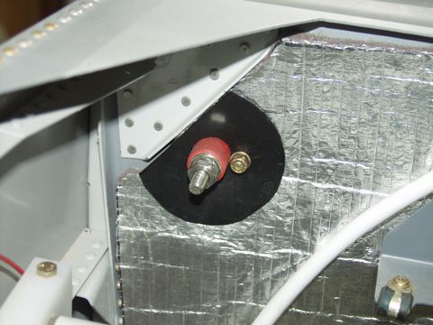
I started running the large wires as well. The red thing on the firewall is a pass-through that I got from a marine supply. It provides a safe way to route the positive side of the battery through the firewall.
|
 |
| |
|
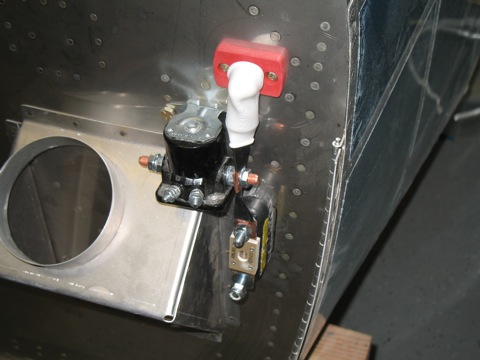
This is the inside of the firewall. The pass-through will eventually be connected to the 2awg wire. I was a bit concerned about the foil on the insulation material, so I made a giant washer out of a piece of plastic.
|
 |
| |
|
4/20/10 - Big Wires - 2 hours
Today I received some parts from McMaster-Carr that I've been waiting on. The first item was a piece of copper bar that I'm using to attach the starter contactor to the firewall pass-through and to the ANL-60. The bar is 5/8" wide and .063" thick. I cut two pieces and bent them 90° and drilled holes for the studs. Doing it this way means I don't have to try to fabricate insanely short wires, which is good. |
 |
| |
|
I also received some rubber grommets that are exactly the right size for installing my brake lines.
|
 |
| |
|
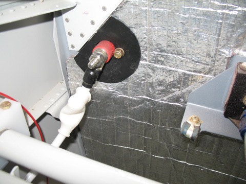
I also used one of these grommets to rout the big power wire up to the firewall. Here is the 2awg wire being attached to the firewall pass-through.
|
 |