Previous: Section 36-37 |
| |
|
Finishing Kit
I'm not really sure where the fuse kit ends and the finishing kit begins, but now seems to be about the time that you'd have to stop if you didn't have the stuff in the finishing kit, so I think I'll call this the beginning of the finishing kit section.
Looking through the instruction manual at this point I realize that up until this point I've been building structural things, and now I am going to be doing a lot less of that and a lot more of the systems things. Things like wiring and fuel lines and push tubes and flaps. Also there's going to be a lot of fiberglass work to do, which can be fun but is also slow and messy. |
| |
|
1/17/09 - Section 38 - 6 hours
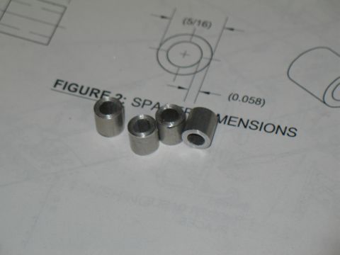
These little spacers caused me some trouble until I woke up. I was trying to cut them on the bandsaw and everytime I would get almost through, the bandsaw blade would grab the small piece and throw it across the workshop, never to be seen again. Then I finally realized that if I held the small piece with some pliers I could be sure I had a useful piece when I was finished with the cut. Amazing.
Anyways, after cutting these I cleaned them up by chucking them in the drill press and running a file and some sandpaper on each of the ends until they were smooth and true. |
 |
| |
|
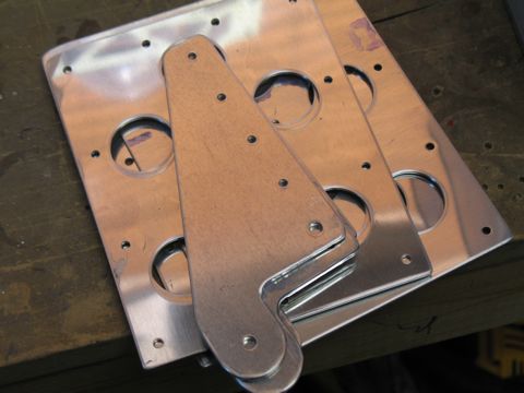
These are some of the parts of the brake pedals. I deburred the edges while watching college hoops. |
 |
| |
|
Assembly is easy as long as you make sure you build two left and two right pedals.
|
 |
| |
|
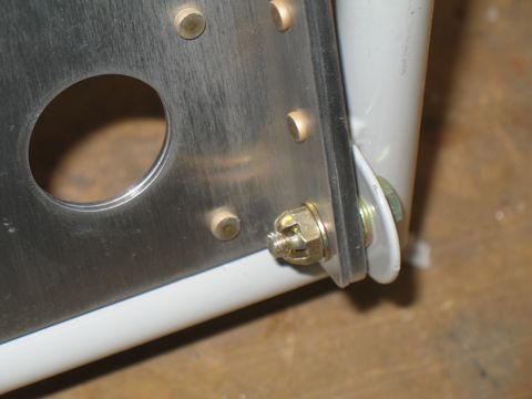
Here I have deviated from the plans slightly. The plans call for AN470 rivets on the surface of the pedals. I will be using AN426 flush head rivets on mine because I think it's better. These rivets only hold the doubler onto the pedal anyways and with flush rivets I can later add some of that non-slip stuff to the face of each pedal.
Also you'll notice that I haven't used any primer or paint on these. That's because these are going to get a lot of wear and tear, and I didn't want the paint all scuffed and peeling. Besides, the raw aluminum look is kinda cool. |
 |
| |
|
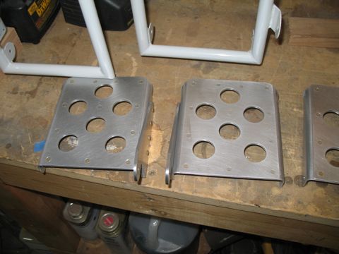
Here are the pedals all riveted and ready to be mounted. |
 |
| |
|
1/18/09 - Brake Stuff - 4 hours
I did this while watching the Arizona Cardinals beat the Eagles to advance to play the Steelers in Super Bowl 43. I love underdogs.
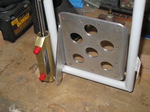
This is the first time in this project that I get to install castle nuts and cotter pins. Just make sure not to tighten them too much. The pedals need to move freely.
|
 |
| |
|
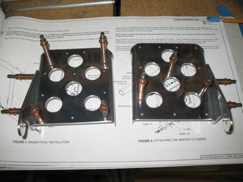
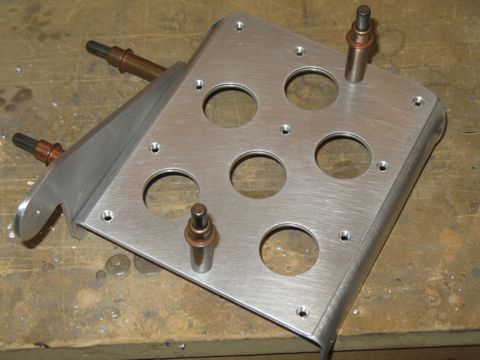
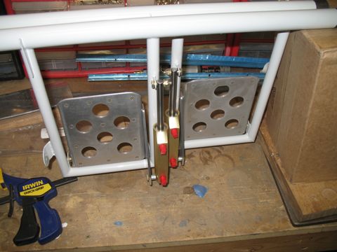
Here is one pedal with the master cylinder attached. Only three more to go. |
 |
| |
|
| |
 |
| |
|
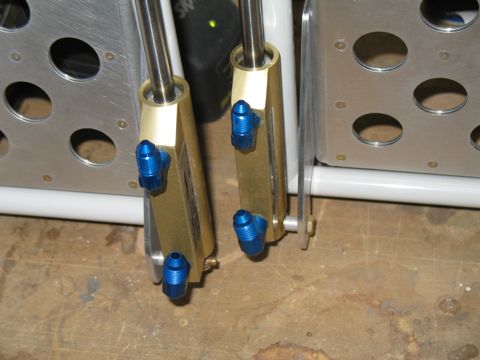
Here's another deviation from the plans. I am replacing the teflon brake lines with some nice braided stainless lines I bought from Bonaco. This requires me to install AN compression fittings in place of the brass bushing fittings that are used with the teflon ones. |
 |
| |
|
Also, I received an order I had placed with Van's last week that included some straight nipple fittings to go into the Matco parking brake thingy.
|
 |
| |
|
1/21-2/7 - Pedals - 10 hours
I just realized that I didn't take any pictures of the steps required to install the pedals into the plane. It went fairly easily once I figured out that the UHMW blocks should be installed on the ends of the pedal subassembly and then mount the whole thing into the plane, instead of the other way around. I had to use a mallet to "encourage" the ends of the rudder pedals to go into the bearing blocks.
I also cut my firewall insulation into pieces that could be fit nicely onto the firewall. I plan to affix these with the red Permatex stuff. |
 |
| |
|
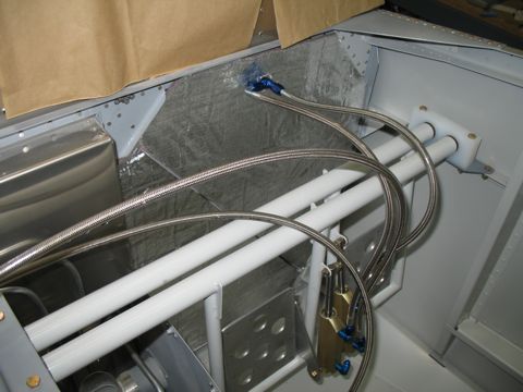
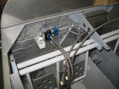
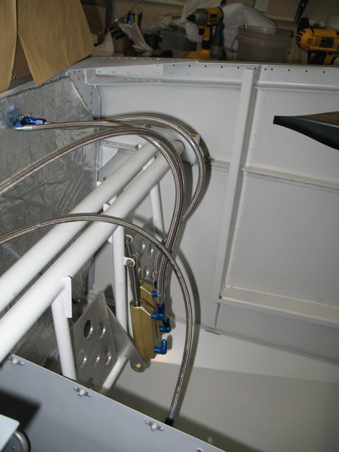
The other thing that you will notice from these photos is the cool Bonaco brake lines that I got to replace the nylon ones that come in the kit. These are braided steel with a plastic coating. I like them a lot.
I still need to figure out how I'm going to rout these through the center pedal support. |
 |
| |
|
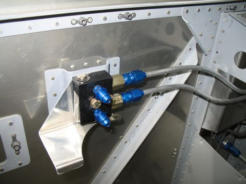
The set I got from Bonaco included new fittings for attaching to the brake fluid reservoir as well. It also includes braided lines to go down the gear legs.
|
 |
| |
|
2/8/09 - Rudder cables - 2 hours
Installation of the rudder cables is straightforward, but getting them secured inside the tailcone requires a contortionist. These adel clamps have a mind of their own anyway, and add that to the tight quarters at the back of the plane and you have a recipe for frustration. As usual I finally prevailed, but not without a lot of stress. |
 |
| |
|
I have some nice aluminum cover plates that I need to install over these.
|
 |
| |
|
This is a picture of the inside of the tunnel where the rudder cable exits. Again, I have some little covers for the outside of the tunnel.
Since I don't have the rudder attached I can't hook up the cable and make the attachment at the pedals. I'll have to delay that for a while. |
 |
| |
|
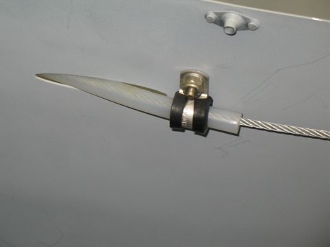
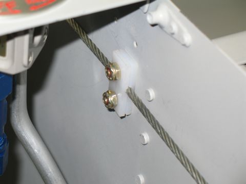
2/13/09 - Cable Guides - 2 hours
I have a question about these cable guides. When I install them they are tight around the cable. They almost lock the cable. So I'm wondering if they will loosen up with wear, or if I need to ease off on tightening the nuts. |
 |
| |
|
The screws are precariously close to the front seat bulkhead making it difficult to get a screwdriver in there.
|
 |
| |
|
2/13/09 - Section 39 - 5 hours
This was a fun section, so naturally there will be more pictures.
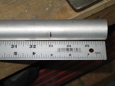
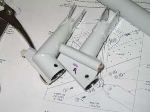
Starting with the pushrods. After searching for all the rod ends and bearings and such, I cut and drilled the ends of the first pushrod. The first one is a short tube that goes from the control stick subassembly back to the middle of the cabin. |
 |
| |
|
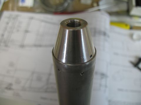
Since the rod end bearing on the front of this pushrod extends more than half of it's threaded area past the rod end, it needs to be drilled so safety wire can be installed. I inadvertently drilled both ends, but it doesn't matter.
|
 |
| |
|
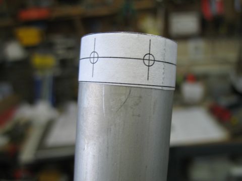
To drill the holes in the ends of the tubes, Van's has you cut out a little template that gets wrapped around the tube. It has markings to show you where to drill. Using my center punch I marked where each hole needed to be drilled, and then I set up my drill press with a little cradle so I could easily position the tube for drilling.
|
 |
| |
|
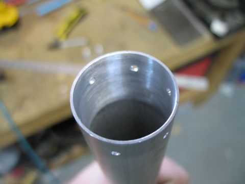
Here is one end, all nice and drilled.
|
 |
| |
|
Next, the rod ends are inserted and then match-drilled. These little suckers go in tightly, so I did them one at a time so I could insert a pipe through the other end and "push" the rod-end out of the tube after it was drilled.
|
 |
| |
|
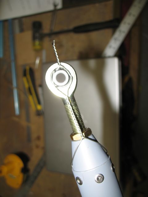
After that came some deburring and priming, and then I could rivet the rod ends in place.
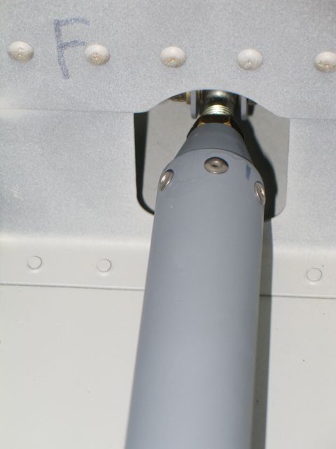
Here is how the safety wire is installed on the front end of the forward pushrod.
I repeated most of this process for the other, larger pushrod. |
 |
| |
|
2/14/09 - More Pushrods - 7 hours
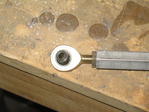
There are some smaller interconnecting rods made from premade hexagonal aluminum tubing stuff. The hardest part of these are finding the correct rod end bearings and jam nuts. |
 |
| |
|
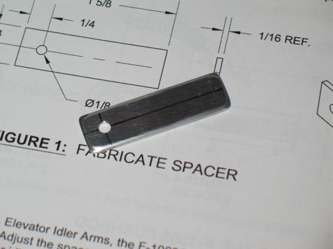
Here's a spacer. Wow.
|
 |
| |
|
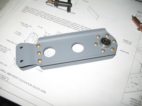
It goes in this thing. It's called an idler arm and it goes in the fuselage tunnel to redirect the elevator pushrod. It has a bearing at the top and some holes at the bottom where rod end bearings will eventually be bolted. You'll see.
|
 |
| |
|
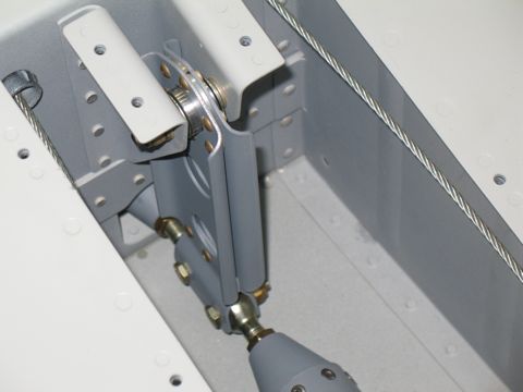
Like this...
|
 |
| |
|
| |
 |
| |
|
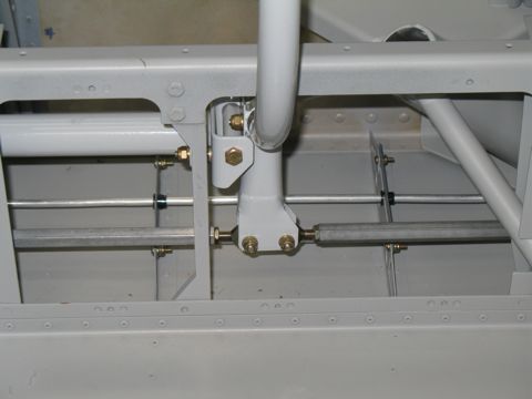
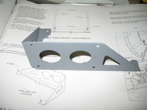
With the pushrods in place I finally get to install the control sticks. These need to be match-drilled to the bases, pictured.
The hardest part is getting the stick inserted far enough into the shaft of the base. On mine I had to use a Dremel to remove some of the weld residue on the inside of the base. |
 |
| |
|
Well as you can see I skipped a bunch of pictures. That usually means that it was difficult work. In this case it means that I was watching a basketball game and didn't think to take pictures.
There are brass rods that need to fit snugly in the ends of the control column. They need to slide loosely into the control stick bases, and the control stick base needs to be slightly smaller and travel freely in the end of the control column. So after about fifty test fits and subsequent trips to the grinder, here is the result. |
 |
| |
|
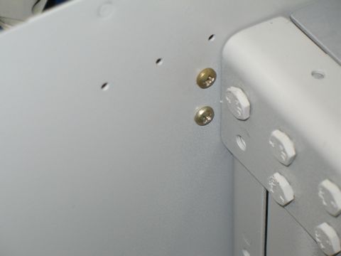
Here you can see the aileron pushrods as they extend out of the fuselage. Also, you might notice (if you really squint) that there is a castellated nut on the control column. I have inserted a cotter pin but haven't secured it yet because I'm still playing with the fit.
Also not pictured is the process of squaring the sticks to each-other. This is done by loosening or tightening the rod ends. |
 |
| |
|
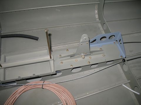
2/15/09 - Autopilot bracket - 2 hours
I drilled and deburred the bracket for the pitch servo. |
 |
| |
|
Then I installed it, along with the elevator/battery tray assembly, into the tailcone.
After this step I had to spend some time adjusting the rod ends so the bellcrank is in neutral position when the stick assembly is also in neutral position.
Next: Section 40 - Flaps |
 |