Previous: Horizontal Stab
9/1/06 - 9/4/06 - Elevators - 10 hours
I had to take some time away from the project to build some bookshelves. The woodworking skills are getting a bit rusty, but I finally prevailed, so now I can get back to the RV.
It's Labor Day weekend and college football is just starting up, so I was able to spend a good amount of time this weekend working on the elevators.
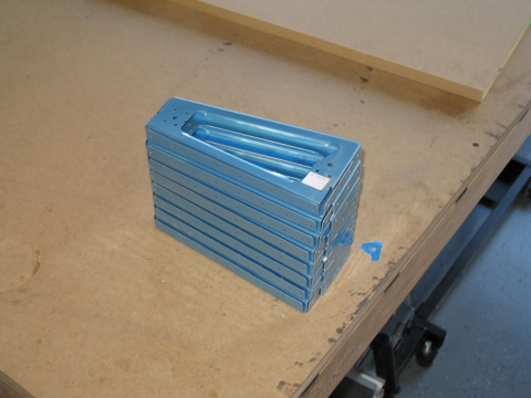
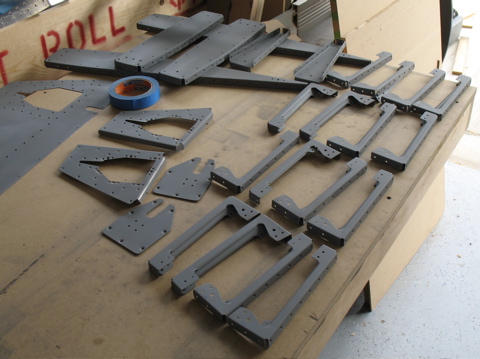
Here are the uncut ribs for the two elevators. They need to be cut in half. |
|
| |
|
I used Wiss snips to cut these apart. I have found that the bandsaw likes to grab ahold of this thin aluminum and do nasty things to it. The snips leave a rough edge, but at least I don't mangle any parts.
|
 |
| |
|
After they are cut, they are rejoined to form one rib.
|
 |
| |
|
I turned my attention to the tip ribs for a bit. These things need to have the flanges fluted. In this fuzzy photo you might be able to see the gap between the ends. This was dealt with by fluting the flanges.
|
 |
| |
|
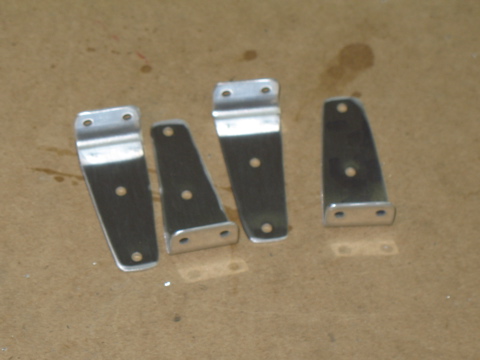
These are clips that are used to reinforce the aft edges of the elevators. They were cut out on the bandsaw.
|
 |
| |
|
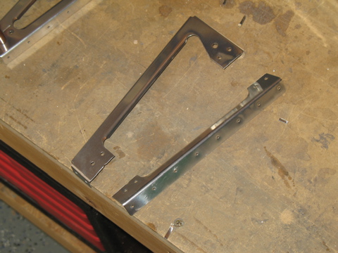
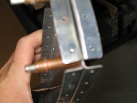
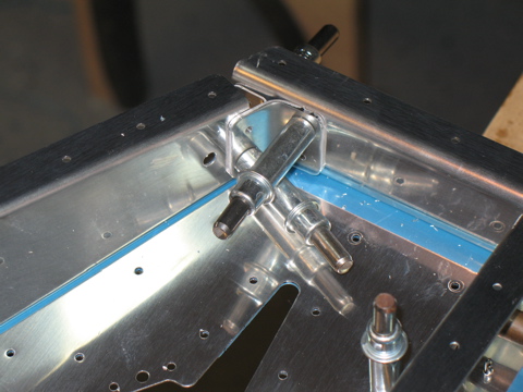
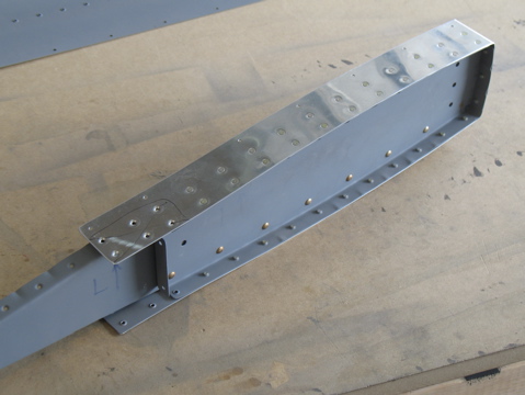
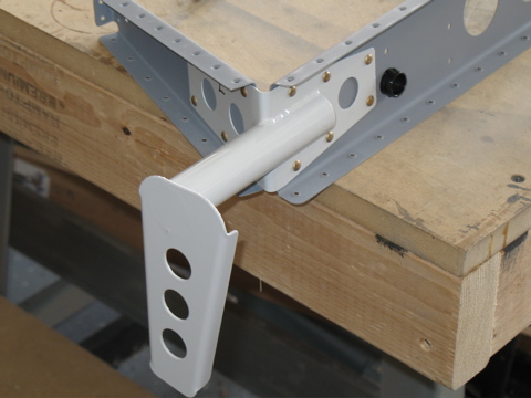
Here is one of the counterbalance arms preassembled. There will eventually be weights mounted to the end of this thing, which will make it easier to move the elevators up and down and reduce the potential for flutter.
|
 |
| |
|
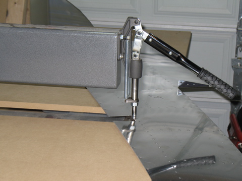
See these tabs? They had to be bent by me. I used the hand seamer to make the bends. You can get really serious about bending these tabs by mounting blocks of wood or whatever to the skin, but the bottom line is that they need to be bent up or down to form the end cap for the elevator where the trim tab begins.
|
 |
| |
|
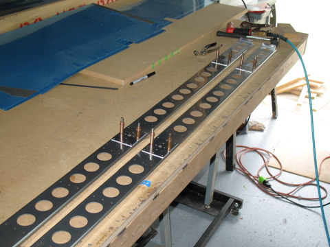
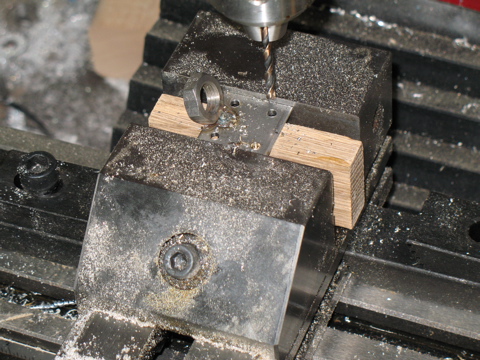
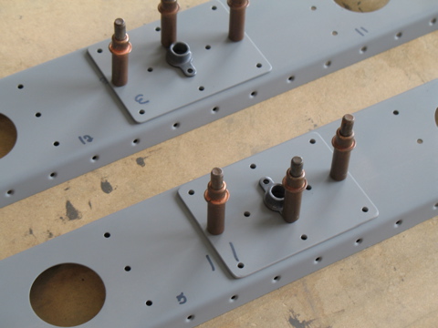
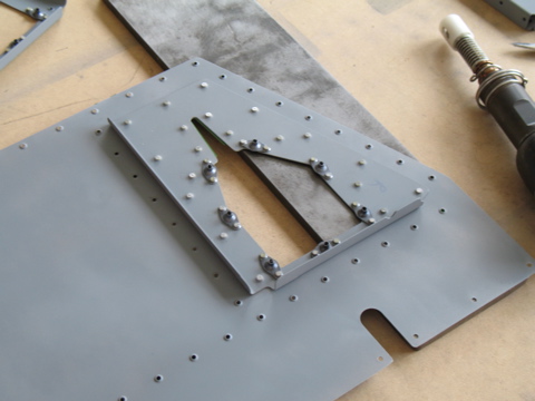
On to the spars. Doubler plates are installed at the points where there will eventually be rod-end bearings installed. These bearings are the "hinges" which allow the elevators to move.
Right now I'm just match-drilling the doublers. After I drilled them I marked their locations and then put them away. |
 |
| |
|
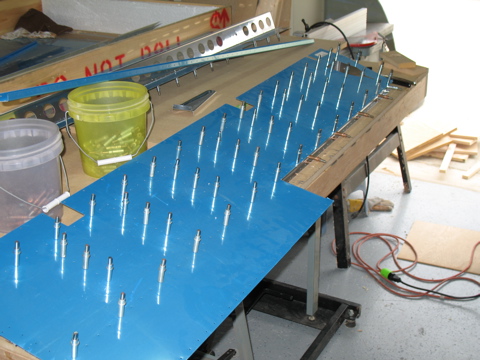
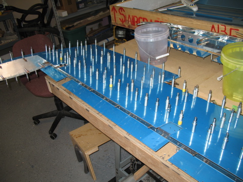
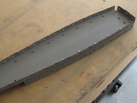
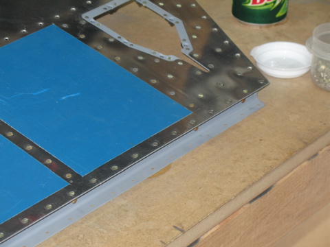
This is the bottom of the right elevator. It was attached to the skeleton assembly of the ribs and the spars, and then I match-drilled the skin.
The tricky part is realizing the left and right sides, as well as the tops and bottoms. The bottom skins have openings for the trim servo. It's helpful to remember that the trim tab opening is at the root of the elevator. |
 |
| |
|
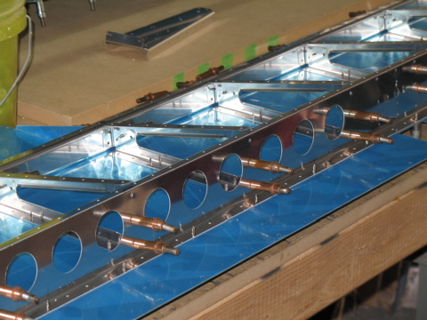
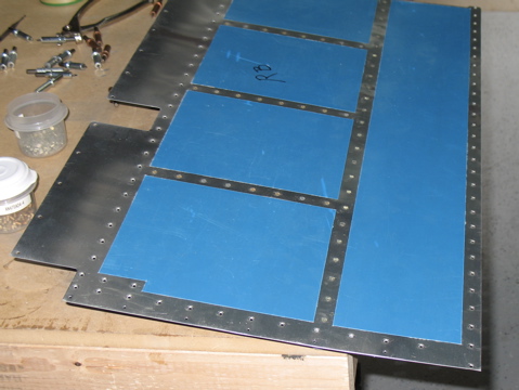
The ribs were also match-drilled to the spars.
|
 |
| |
|
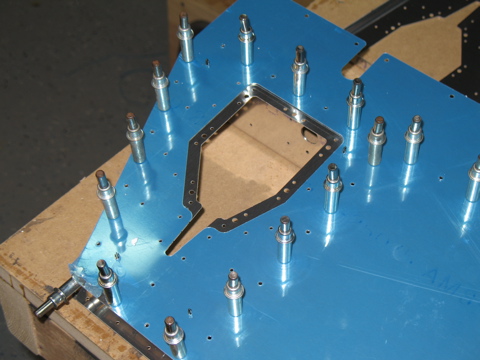
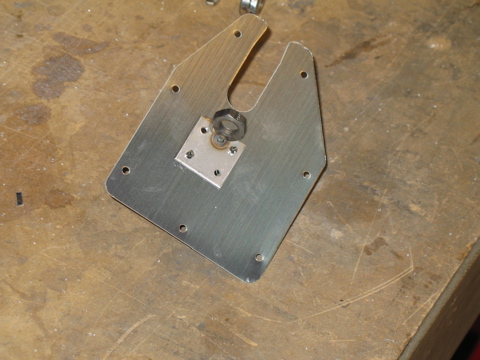
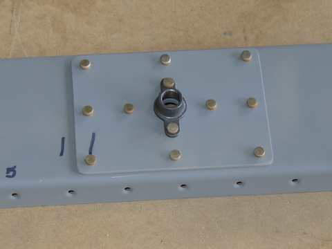
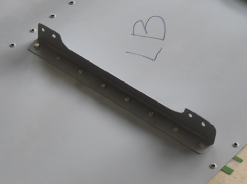
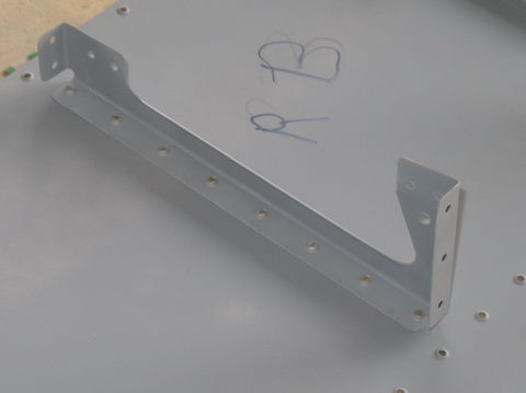
Here we have the doubler plate that will eventually have platenuts installed which will allow the trim tab control cable to be installed.
|
 |
| |
|
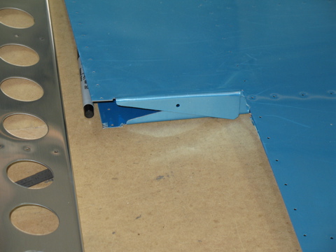
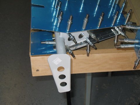
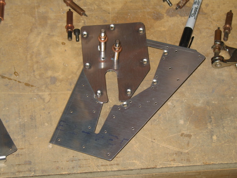
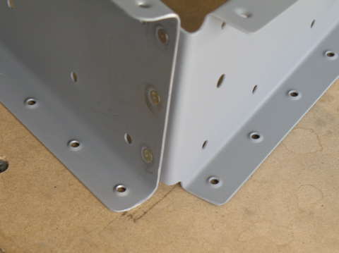
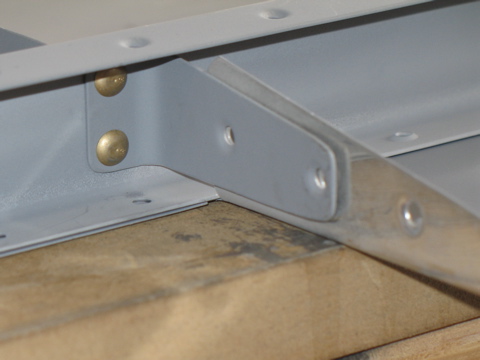
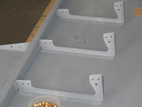
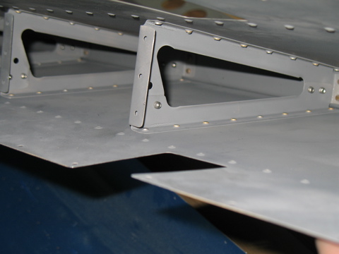
This is a gusset on the aft inboard corner of the elevator. It reinforces the connection between the rear spar and the root rib.
|
 |
| |
|
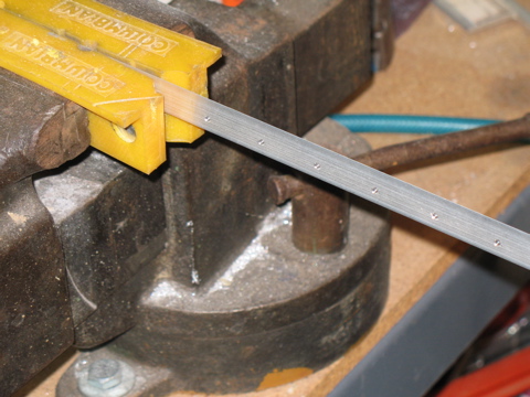
This is the extruded wedge that forms the trailing edge. It must be cut in half to make both sides.
|
 |
| |
|
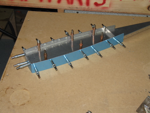
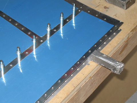
Next I attached the counterbalance assembly and clecoed on the top skin. By the time I had done this for both elevators I had pretty much run out of 3/32" clecoes.
|
 |
| |
|
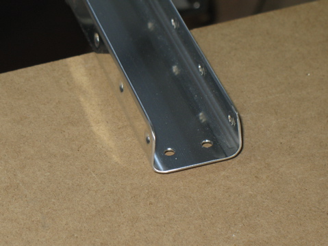
Here's one big improvement over the RV-9A. The holes are pre-drilled where the control horn assembly is to be attached. They are undersized, but they do the job of putting the control horns in the right spot.
|
 |
| |
|
| |
 |
| |
|
| |
 |
| |
|
| |
 |
| |
|
9/5/06 - Deburring - 2 hours
|
 |
| |
|
9/6/06 - 9/8/06 - Dimpling, Etc. - 4 hours
Once again I got to use the DRDT-2 dimpler. This thing is just great! It lets me dimple the skins without making so much noise with the mallet. |
 |
| |
|
The rear spars also got dimples, but I did these with the pneumatic squeezer.
|
 |
| |
|
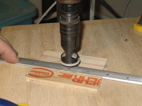
The trailing edge material needs to be countersunk so the dimples in the skins can sit down flush. To make these, I made a little jig on the drill press table. What you don't see is the piece of scrap wedge material underneath the trailing edge. It has a hole in it to account for the pilot on the countersink bit.
So the way it works is the trailing edge sits on top of the scrap piece, making the surface of the wedge sit perpendicular to the countersink.
After this I spent a long time scuffing parts for priming. |
 |
| |
|
9/16/06 - Priming, Assembly - 6 hours
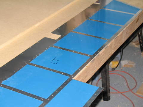
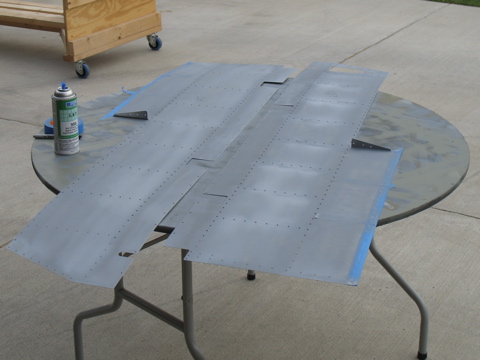
I used the rattle can primer for this stuff because I didn't feel like dragging out the spray equipment. The rattle cans work pretty well on small pieces but not so good on skins. You may notice some masking tape on the trailing edges. This is to keep the metal clean for when I eventually bond the trailing edges with ProSeal. |
 |
| |
|
After quite a bit of work scuffing and cleaning and then priming, I got all of the pieces back inside.
One thing that's a bit tricky is to make sure I don't cover up my numbers that I've written on each part. So, after cleaning the parts I had to re-write the number on the part. Fortunately the sharpie shows through the primer, so I don't have to rewrite the numbers after priming. |
 |
| |
|
Now for some assembly (finally) starting with the counterbalance ribs.
|
 |
| |
|
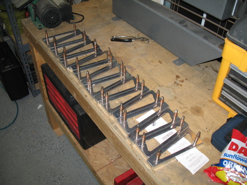
After some quality time with a rivet squeezer, I soon had two nicely completed counterbalance arms.
|
 |
| |
|
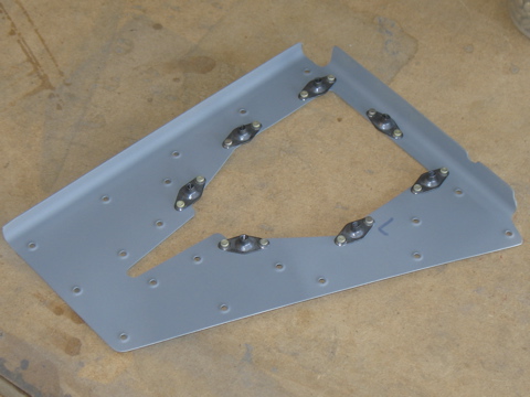
Now we turn to the main spars. You can see my numbering system on the spars. I found the matching doubler plates and installed platenuts.
|
 |
| |
|
Here is one of the end ribs with the flush rivets on the forward side of the main spar.
|
 |
| |
|
| |
 |
| |
|
| |
 |
| |
|
| |
 |
| |
|
| |
 |
| |
|
| |
 |
| |
|
| |
 |
| |
|
9/17/06 - Assembly - 4 hours
I did lots of riveting these past couple of days. The ribs are installed. The aft spar is riveted to the ribs. |
 |
| |
|
| |
 |
| |
|
| |
 |
| |
|
| |
 |
| |
|
Here's something new. The instructions call for a special bucking bar that is about 12" long and has a weird face on one end. Well, I wasn't going to go buy a bucking bar just for this one situation, so I used a bucking bar I already have. It's one that looks sort of like a railroad spike. It is probably 8" long and is tapered at one end.
|
 |
| |
|
Next: Elevators Part 2 |
 |
| |
|
| |
|